– 6 –
LIST OF FIGURES
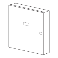
Figure 1. Installing the Cabinet Lock .................................................................................. 11
Figure 2. Installing The PC Board Alone, or (if used), With a 4204, 4219, or 4229............ 12
Figure 3. Installing the PC Board & RF Receiver (if used) Together in the Cabinet........... 13
Figure 4. Standard Telephone Line Connections ............................................................... 14
Figure 5. Keypad Connections to the Control Board .......................................................... 16
Figure 6. Using a Supplementary Power Supply for Keypads............................................ 17
Figure 7. 4-Wire Smoke Detector Connections to Zone 5.................................................. 19
Figure 8 Wiring Connections, 4219 & 4229 (4229 shown) ................................................ 23
Figure 9. 5881, and 5882 Wireless Receivers (cover removed) ........................................ 29
Figure 10 . 4204 Connections To Control.............................................................................. 44
Figure 11. 4229 Connections To Control.............................................................................. 45
Figure 12. FA4285 Phone Module Wiring Connections ....................................................... 52
Figure 13. Typical Sounder Wiring ....................................................................................... 56
Figure 14. Long Range Radio Connections ......................................................................... 57
Figure 15. Connection of AAV Unit When Not Using an FA4285 Phone Module ................ 59
Figure 16. Connection of AAV Unit When Also Using an FA4285 Phone Module ............... 59
Figure 17. FA142C Summary of Connections Diagram .............................. Inside Back Cover