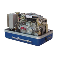
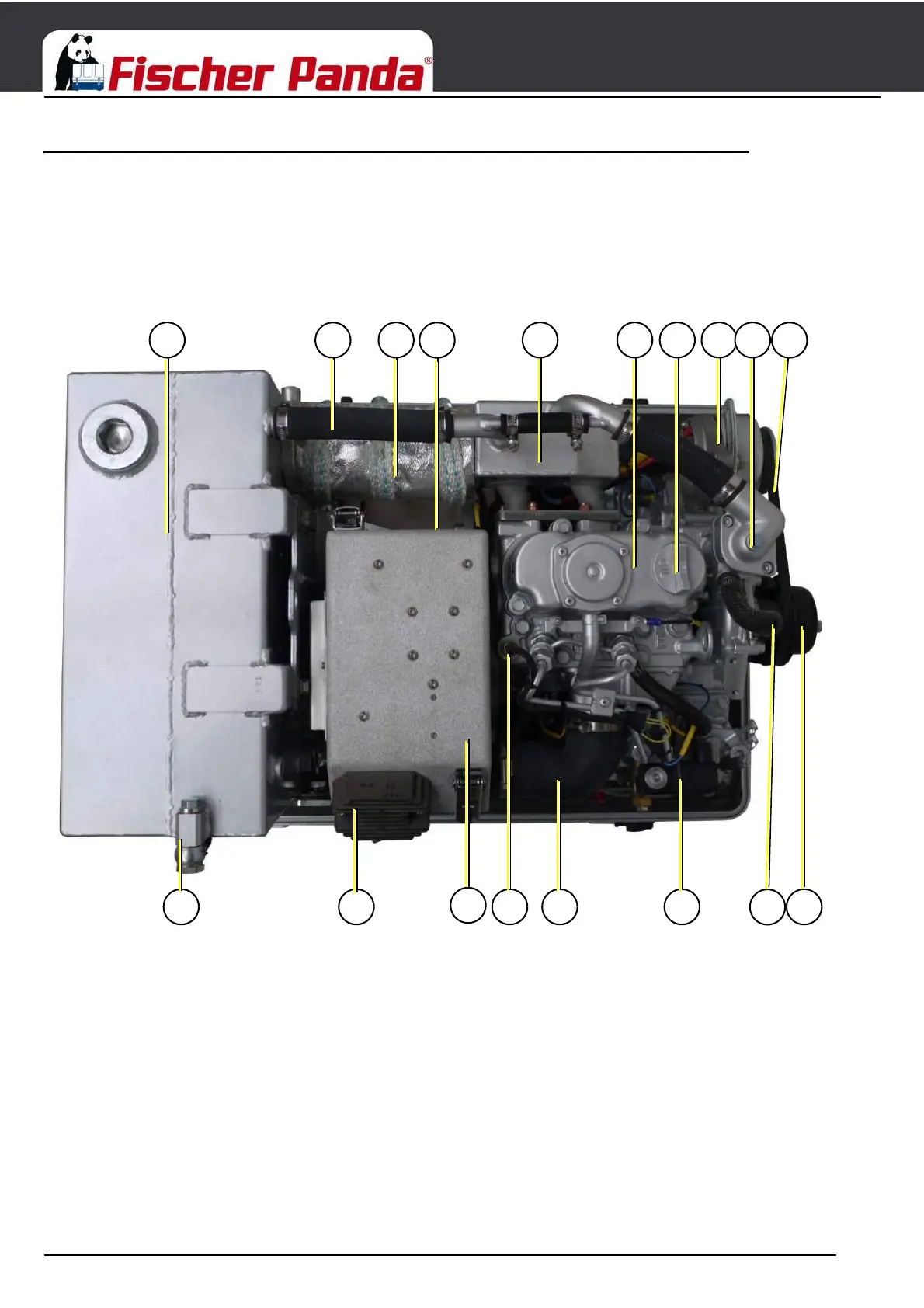
Fig. 4.1.6-1: View from above
01) Ventilation hose to external expansion tank
02) Charge controller for DC-alternator
03) Air suction housing
04) Thermoswitch cylinder head
05) Suction hose, air suction housing - induction elbow
06) Fuel solenoid valve
07 Ventilation screw internal cooling water pump
08) Pulley for internal cooling water pump
09) V-belt
10) Ventilation screw thermostat housing
11) DC-alternator
12) Oil filler neck with cap
13) Valve cover
14) Watercooled exhaust elbow
15) Actuator power modul
16) Compensator under heat isolation
17) Cooling water pipe
18) Pre-silencer