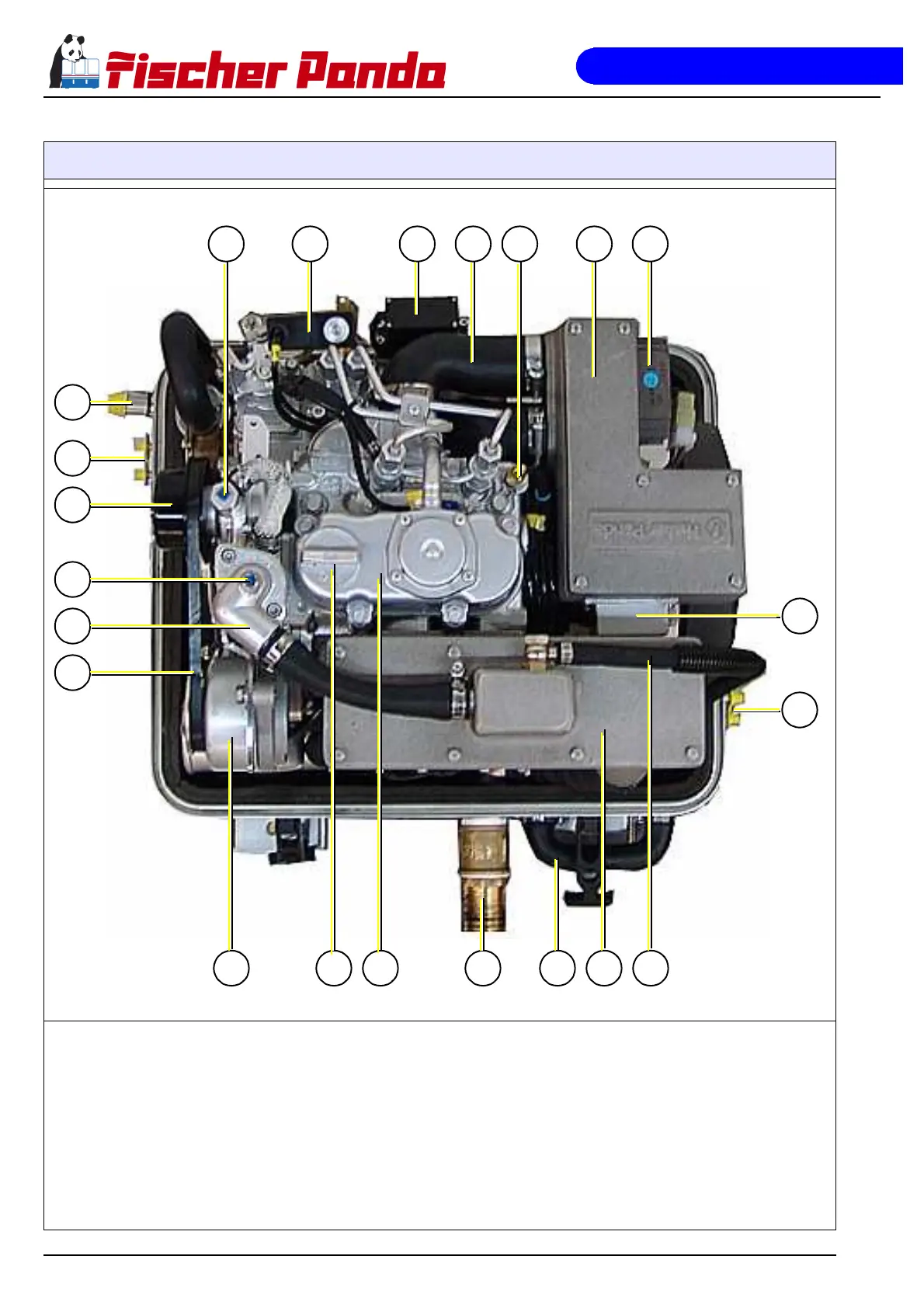
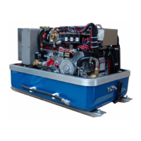
Fig. B.2.5-1: View from above
01) Raw water intake
02) Fuel connections
03) Pulley for internal cooling water pump
04) Ventilation screw thermostat housing
05) Thermostat housing
06) V-belt
07) DC-alternator 12V
08) Oil filler neck with cap
09) Valve cover
10) Exhaust outlet
11) Connection for external ventilation valve
12) Watercooled exhaust elbow
13) Ventilation pipe to external expansion tank
14) Connections external expansion tank
15) Actuator power modul
16) Charge controller for DC-alternator
17) Air suction housing
18) Thermoswitch cylinder head
19) Suction hose, air suction housing - induction elbow
20) Actuator
21) Fuel solenoid valve
22) Ventilation screw internal cooling water pump


 To Next Page