Instruction Manual
D103176X012
Detailed Setup and Calibration
June 2017
14
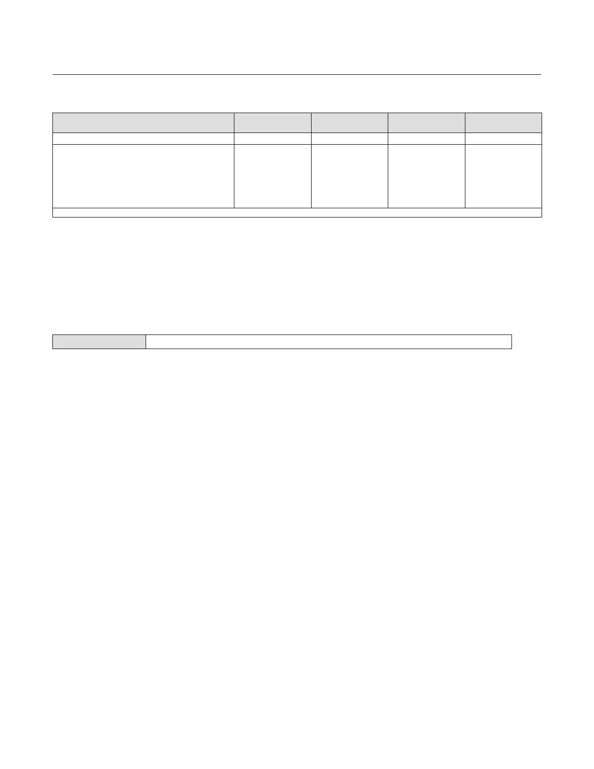
Table 2‐3. Conditions for Modifying FIELDVUE DVC2000 Digital Valve Controller Parameters
Parameters
In Service/
Config Protected
In Service/
Config Unprotected
Out of Service/
Config Protected
Out of Service/
Config Unprotected
Drive Alert Enable n n n n
Flash ROM Fail
Ref Voltage Fail
Drive Current Fail
Critical NVM Fail
Temp Sensor Fail
Press Sensor Fail
Tvl Sensor Fail
- - -
- - -
- - -
- - -
- - -
- - -
- - -
- - -
- - -
- - -
- - -
- - -
- - -
- - -
- - -
- - -
- - -
- - -
- - -
- - -
- - -
n
n
n
n
n
n
n
n—indicates parameter may be modified for instrument mode and protection shown.
To change an instrument's protection, press the Hot key on the Field Communicator display window and select
Protection or select Protection from the Detailed Setup menu. Select the desired level of protection. Follow the prompts
on the Field Communicator display to set the protection level.
General Information
Field Communicator Setup & Diag > Detailed Setup > General (1-2-3)
Follow the prompts on the Field Communicator to enter or view information in the following fields:
D HART Tag—Enter an up to 8 character HART tag for the instrument. The HART tag is the easiest way to distinguish
between instruments in a multi-instrument environment. Use the HART tag to label instruments electronically
according to the requirements of your application. The tag you assign is automatically displayed when the Field
Communicator establishes contact with the digital valve controller at power-up.
D Message—Enter any message with up to 32 characters. Message provides the most specific user-defined means for
identifying individual instruments in multi-instrument environments.
D Descriptor—Enter a descriptor for the application with up to 16 characters. The descriptor provides a longer
user-defined electronic label to assist with more specific instrument identification than is available with the HART
tag.
D Date—Enter a date with the format MM/DD/YY. Date is a user-defined variable that provides a place to save the date
of the last revision of configuration or calibration information.
D Valve Serial Num—Enter the serial number for the valve in the application with up to 12 characters.
D Inst Serial Num—Enter the serial number on the instrument nameplate, up to 12 characters.
D Polling Address—If the digital valve controller is used in point-to-point operation, the Polling Address is 0. When
several devices are connected in the same loop, such as for split ranging, each device must be assigned a unique
polling address. The Polling Address is set to a value between 0 and 15. To change the polling address the
instrument must be Out Of Service.
For the Field Communicator to be able to communicate with a device whose polling address is not 0, it must be
configured to automatically search for all or specific connected devices.
D LUI Language—Select the language to be displayed on the local user interface; English, French, German, Italian,
Spanish, Chinese and Japanese.
 Loading...


