Instruction Manual
D103176X012
Detailed Setup and Calibration
June 2017
13
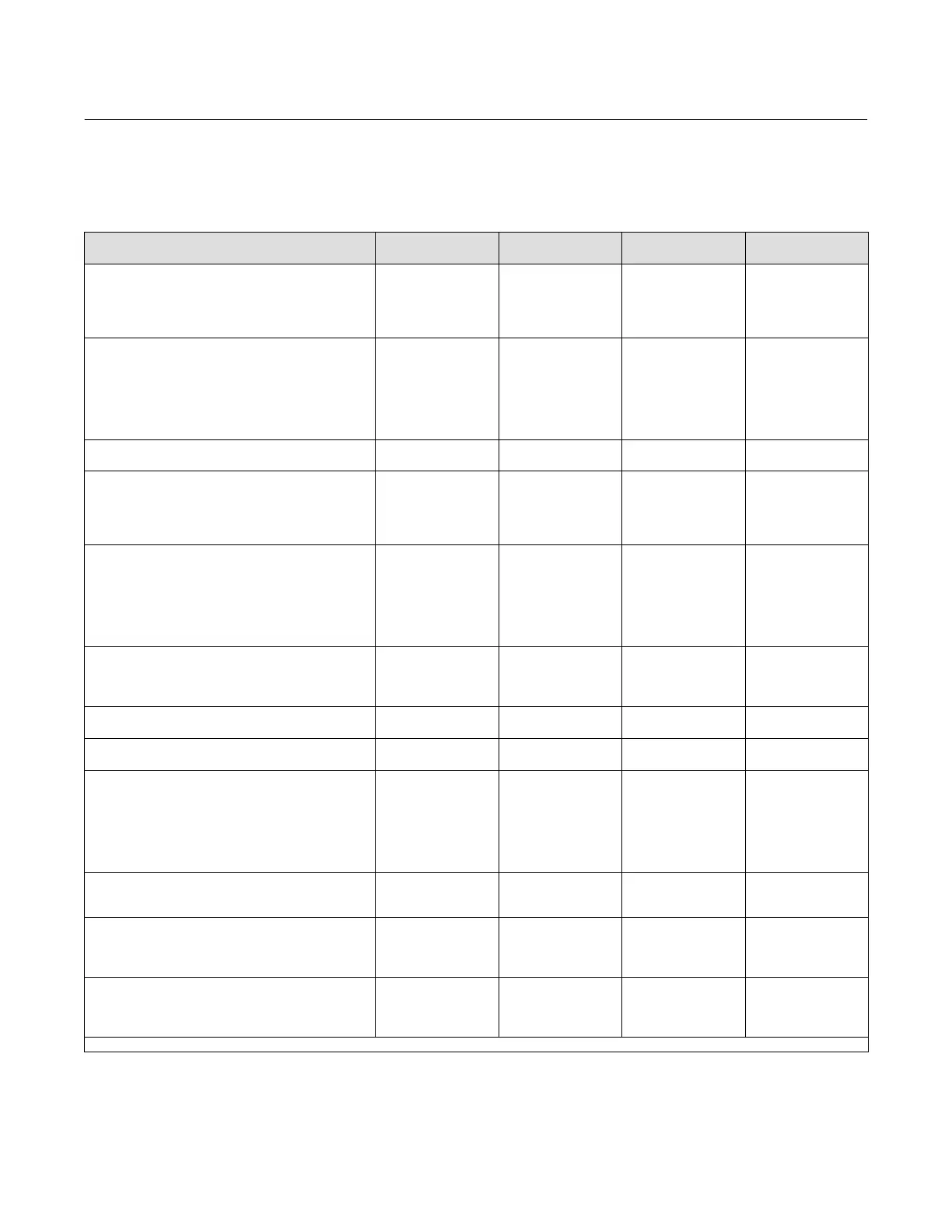
Table 2‐3 lists configurable parameters in the instrument and the requirements for modifying these parameters, in
terms of instrument mode and protection.
Table 2‐3. Conditions for Modifying FIELDVUE DVC2000 Digital Valve Controller Parameters
Parameters
In Service/
Config Protected
In Service/
Config Unprotected
Out of Service/
Config Protected
Out of Service/
Config Unprotected
Control Mode
Restart Ctrl Mode
Burst Mode Enable
Burst Mode Command
Protection
- - -
- - -
n
- - -
n
- - -
- - -
n
- - -
n
n
- - -
n
- - -
n
n
n
n
n
n
HART Tag
Message
Description
Date
Valve Serial Num
Inst Serial Num
Polling Address
- - -
- - -
- - -
- - -
- - -
- - -
- - -
n
n
n
n
n
- - -
- - -
- - -
- - -
- - -
- - -
- - -
- - -
- - -
n
n
n
n
n
n
n
Max Supply Pressure
Zero Ctrl Signal
- - -
- - -
- - -
- - -
- - -
- - -
n
n
Analog In Units
Input Range High
Input Range Low
Pressure Units
Temp Units
- - -
- - -
- - -
- - -
n
- - -
- - -
- - -
- - -
n
- - -
- - -
- - -
- - -
n
n
n
n
n
n
Tuning Set
Prop Gain
Velocity Gain
MLFB Gain
Input Char
Define Custom Char
Set Pt Filter Time
- - -
- - -
- - -
- - -
- - -
- - -
- - -
n
n
n
n
- - -
- - -
- - -
- - -
- - -
- - -
- - -
- - -
- - -
- - -
n
n
n
n
n
n
n
Tvl Limit High
Tvl Limit Low
Tvl Cutoff High
Tvl Cutoff Low
- - -
- - -
- - -
- - -
- - -
- - -
- - -
- - -
- - -
- - -
- - -
- - -
n
n
n
n
Min Opening Time
Min Closing Time
- - -
- - -
- - -
- - -
- - -
- - -
n
n
Integral Gain
Integral Deadband
- - -
- - -
n
n
- - -
- - -
n
n
Tvl Hi/Lo Enab
Tvl HH/LL Enab
Tvl Alert Hi Pt
Tvl Alert Lo Pt
Tvl Alert HiHi Pt
Tvl Alert LoLo Pt
Tvl Alrt DB
n
n
n
n
n
n
n
n
n
n
n
n
n
n
n
n
n
n
n
n
n
n
n
n
n
n
n
n
Tvl Dev Alrt Enab
Tvl Dev Alrt Pt
Tvl Dev Time
n
n
n
n
n
n
n
n
n
n
n
n
Cycl Cnt Alrt Enab
Cycl Count Alrt Pt
Cycl Count DB
Cycl Count
n
n
n
n
n
n
n
n
n
n
n
n
n
n
n
n
Tvl Acum Alrt Enab
Tvl Acum Alrt Pt
Tvl Acum DB
Tvl Acum
n
n
n
n
n
n
n
n
n
n
n
n
n
n
n
n
n—indicates parameter may be modified for instrument mode and protection shown.
-Continued-
 Loading...


