Local Interface Flow Chart/Menu Trees
June 2017
Instruction Manual
D103176X012
62
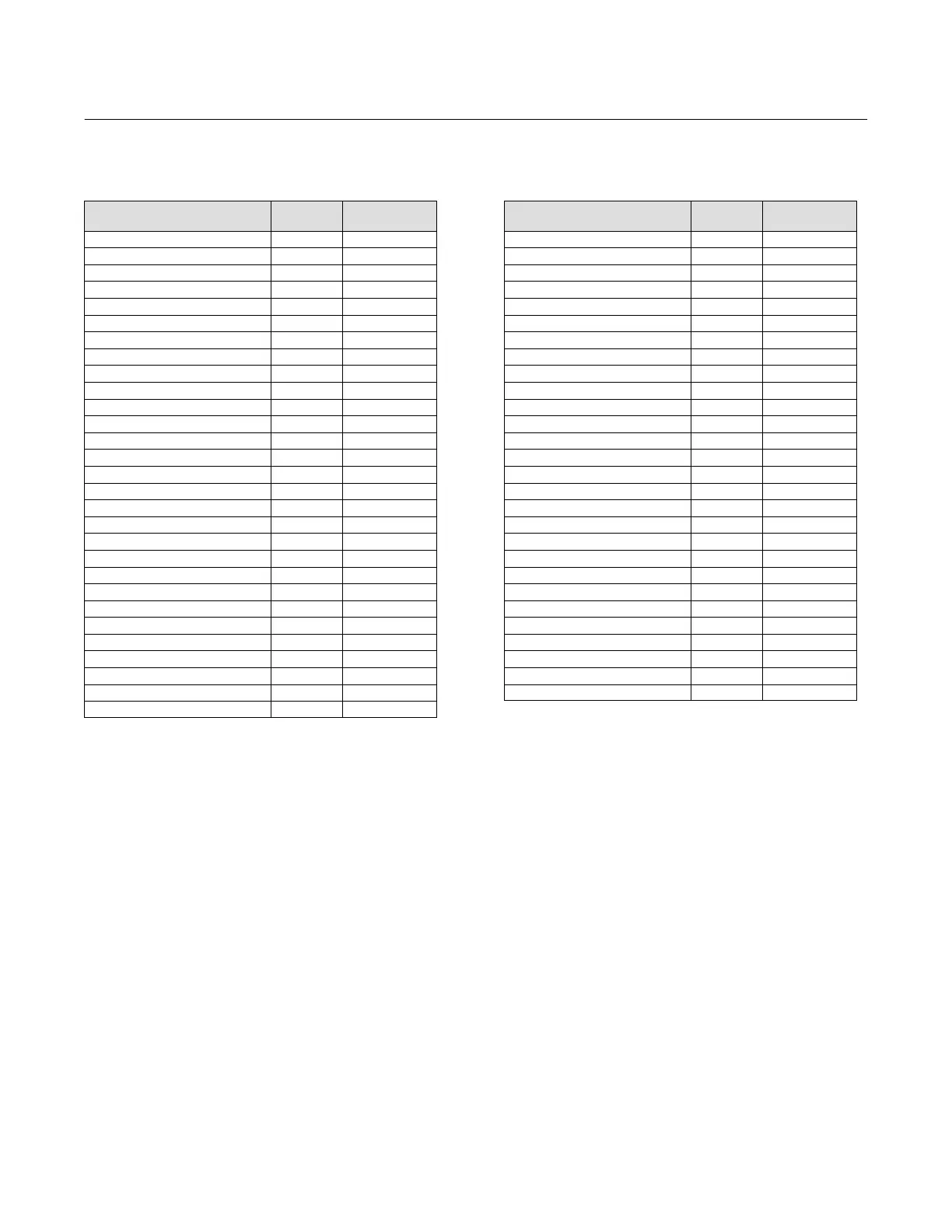
Field Communicator Fast‐Key Sequence (Instrument Level AC)
Function/Variable
Fast‐Key
Sequence
Coordinates
(1)
Analog Input Calibration 1‐3‐1 3-E
Analog Input Units 1‐2‐2‐1 4-E
Auto Calibrate Travel 1‐3‐2 3-E
Auto Setup 1‐1‐1 3-B
Auto Tuner 1‐1‐1‐3 3-B
Basic Setup 1‐1 3-B
Calibrate 1‐3 3-E
Damping Factor 1‐1‐1‐4‐2 5-B
Date 1‐2‐1‐4 4-D
Descriptor 1‐2‐1‐3 4-D
Detailed Setup 1‐2 3-D
Device Description Revision 2‐2 2-F
Device Identification 2‐1‐9 3-F
Device Information 2‐1 3-F
Device Revision 2‐1‐2 3-F
Display 2 1-E
Enable Integral Control 1‐2‐3‐6‐1 6-F
Expert Tuning Gains 1‐1‐1‐4‐3 6-C
Firmware Date 2‐1‐4 3-F
Firmware Revision 2‐1‐3 3-F
HART Tag 1‐2‐1‐1 4-D
HART Universal Revision 2‐1‐1 3-F
Input Characterization 1‐2‐3‐4 4-F
Input Range High 1‐2‐2‐2 4-E
Input Range Low 1‐2‐2‐3 4-E
Instrument Level 2‐1‐8 3-F
Instrument Mode Hot Key 1-A
Instrument Serial Number 1‐2‐1‐6 4-E
Integral Dead Zone 1‐2‐3‐6‐3 6-F
Function/Variable
Fast‐Key
Sequence
Coordinates
(1)
Integral Gain 1‐2‐3‐6‐2 6-F
Integral Settings 1‐2‐3‐6 6-F
LUI Language 1‐2‐1‐8 4-E
LUI Pressure Units 1‐2‐2‐5 4-E
Manual Calibrate Travel 1‐3‐3 3-E
Manual Setup 1‐1‐2 3-B
Measured Variable 1‐2‐2 4-E
Main Electronics Revision 2‐1‐5 3-F
Maximum Supply Pressure 1‐1‐2‐2‐3 5-C
Message 1‐2‐1‐2 4-D
Polling Address 1‐2‐1‐7 4-E
Pressure Units 1‐2‐2‐4 4-E
Protection Hot Key 1-A
Secondary Electronics Revision 2‐1‐6 3-F
Sensor Serial Number 2‐1‐7 3-F
Setup Wizard 1‐1‐1‐1 3-B
Switch 1 Closed
(2)
1‐2‐4‐2 4-G
Switch 1 Trip Point
(2)
1‐2‐4‐1 4-G
Switch 2 Closed
(2)
1‐2‐4‐4 4-G
Switch 2 Trip Point
(2)
1‐2‐4‐3 4-G
Transmitter Action
(2)
1‐2‐4‐5 4-G
Transmitter Calibration
(2)
1‐3‐4 3-E
Travel Cutoff High 1‐2‐3‐5‐1 6-F
Travel Cutoff Low 1‐2‐3‐5‐2 6-F
Tuning Hot Key 1-B
Tuning Set 1‐1‐1‐4‐1 5-B
Valve Serial Number 1‐2‐1‐5 4-E
Zero Control Signal 1‐1‐2‐2‐4 5-C
1. Coordinates are to help locate the item on the menu tree on the facing page.
2. Available only if the instrument has a transmitter and limit switches installed.
 Loading...


