Principle of Operation
June 2017
Instruction Manual
D103176X012
55
Appendix A Principle of OperationA‐1‐
DVC2000 Operation
The DVC2000 digital valve controller uses a traditional 4-20 mA input signal and converts it into a pneumatic output
pressure that is delivered to the control valve actuator. Accurate control of the position of the valve is enabled by valve
stem position feedback. The way in which the DVC2000 accomplishes this is through a two-stage positioner design.
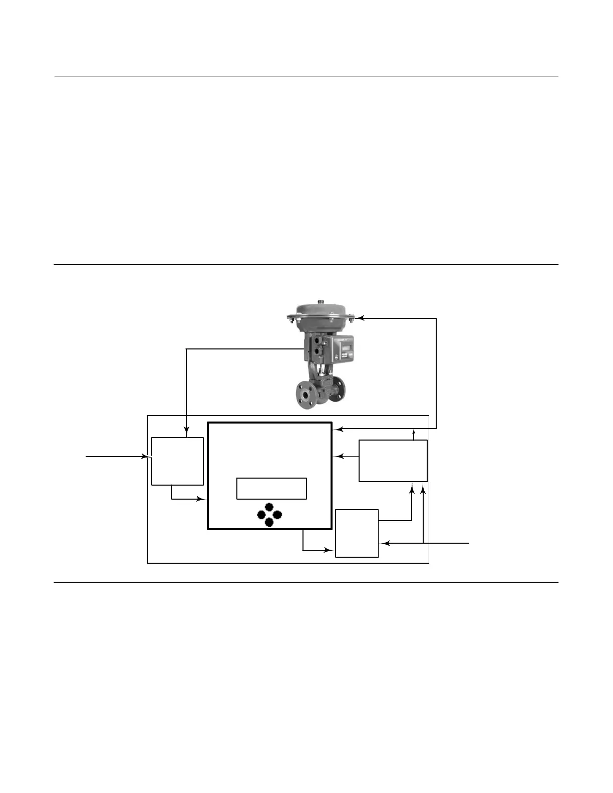
Refer to figure A‐1 for a block diagram of the positioner operation.
Figure A‐1. FIELDVUE DVC2000 Digital Valve Controller Block Diagram
INPUT SIGNAL
(4-20 MA, 9 VOLTS)
TERMINATIONS
&
POSITION
SENSOR
BOARD
MAIN BOARD
ASSEMBLY
ACTUATOR
PRESSURE
SENSOR
TRAVEL = 66.8%
14.6 MA 0.29 BAR
MINOR LOOP
FEEDBACK
DRIVE
SIGNAL
I/P
CONVERTER
(PRE-
AMPLIFIER
AIR SUPPLY
OUTPUT
SINGLE ACTING
RELAY
(POWER
AMPLIFIER)
I/P
PRESSURE
SIGNAL
NON-CONTACT
POSITION FEEDBACK
A traditional 4-20 mA signal provides the set point and power to the instrument. At the same time, the HART protocol
provides instrument and process data through digital communications. The instrument receives this set point and
positions the valve where it needs to be.
D The input signal provides electrical power and the set point simultaneously. It is routed into the terminal board
through a twisted pair of wires. The terminal board contains the termination points for the loop signal (+11/-12). If
the options board is installed, an additional options board set includes additional terminals for the transmitter
output (+31/-32), switch #1 output (+41/-42), and switch #2 output (+51/-52).
D The input signal is then directed to the main electronics board assembly where the microprocessor runs a digital
control algorithm resulting in a drive signal to the I/P converter.
 Loading...


