Instruction Manual
D103176X012
Detailed Setup and Calibration
June 2017
15
Measured Variable Units and Ranges
Field Communicator Setup & Diag > Detailed Setup > Measured Var (1-2-4)
Follow the prompts on the Field Communicator to define the following measured variables units and ranges:
D Analog In Units—Permits defining the Analog Input Units in mA or percent of 4-20 mA range.
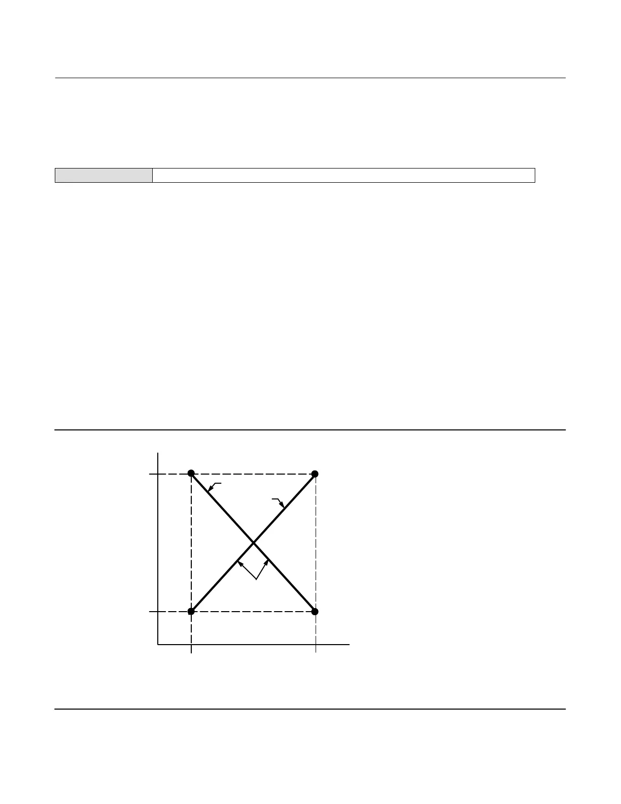
D Input Range Hi—Permits setting the Input Range High value. Input Range High should correspond to Travel Range
High, if the Zero Control Signal is configured as closed. If the Zero Control Signal is configured as open, Input Range
High corresponds to Travel Range Low. See figure 2‐1.
D Input Range Lo—Permits setting the Input Range Low value. Input Range Low should correspond to Travel Range
Low, if the Zero Control Signal is configured as closed. If the Zero Control Signal is configured as open, Input Range
Low corresponds to Travel Range High. See figure 2‐1.
D Pressure Units—Defines the output and supply pressure units in either psi, bar, or kPa.
D LUI Pressure Units—Enter the pressure units displayed on the local user interface; psi, bar, or kPa.
D Temp Units—Degrees Fahrenheit or Celsius. The temperature measured is from a sensor mounted on the digital
valve controller's printed wiring board.
Figure 2‐1. Calibrated Travel to Analog Input Relationship
TRAVEL
RANGE
HIGH
TRAVEL
RANGE
LOW
THE SHAPE OF
THESE LINES DEPENDS ON
THE INPUT CHARACTERISTICS
LINEAR CHARACTERISTIC SHOWN
INPUT RANGE
LOW
INPUT RANGE
HIGH
ANALOG INPUT
MA OR % OF 4-20 MA
CALIBRATED TRAVEL, %
A6531-1
ZCS = CLOSED
ZCS = OPEN
NOTE:
ZCS = ZERO CONTROL SIGNAL

 Loading...


