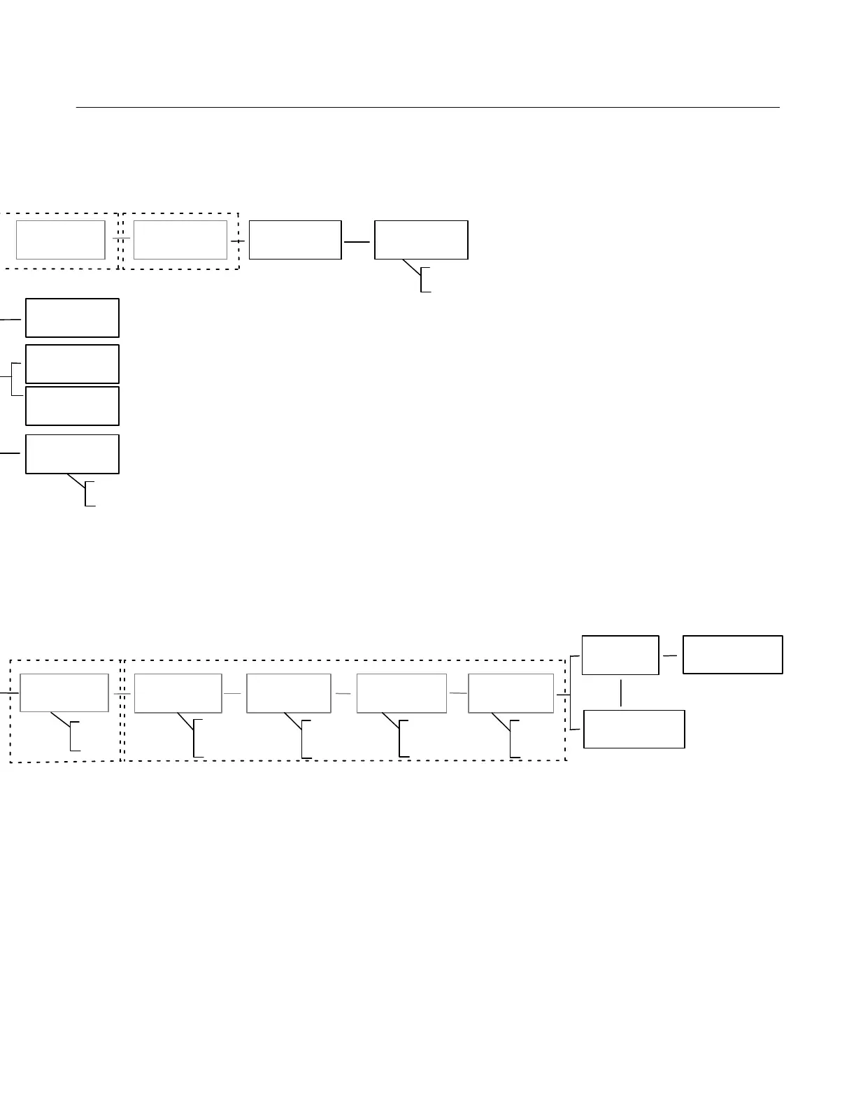
Local Interface Flow Chart/Menu Trees
June 2017
Instruction Manual
D103176X012
59
Y
Y
Y
Y
Y
Y
Y
Y
Y
Y
Y
Y
Y
VALVE MAY MOVE
PRESS FOR 3 SEC
SAVE AND EXIT?
PRESS
EXIT W/O SAVING?
PRESS
SWITCH2 CLOSED
BELOW 10%
Y
Y
Y
Y
SWITCH1 CLOSED
ABOVE 90%
SWITCH2
TRIP POINT 10%
SWITCH1
TRIP POINT 90%
125%
...
-25%
125%
...
-25%
ABOVE
BELOW
DISABLED
BELOW
ABOVE
DISABLED
TRANSMITTER
4 mA CLOSED
CLOSED
OPEN
Only when transmitter / limit switch hardware is installed
Only when transmitter / limit
switch hardware is installed.
1
1
1
1
1
1
1
Y
YY
QUICK SETUP
COMPLETE
SAVE AND EXIT?
PRESS
SAVE AND EXIT? EXIT
W/O SAVING?
CALIBRATION
COMPLETE
CALIBRATION
FAILED
PROTECTION
OFF
OFF
ON
FW3:1, HW1:2
TUNING = C
Y
Y
Y
Y
Only when transmitter / limit switch
hardware is installed
SWITCH1 = OPEN
SWITCH 2 = CLOSED
REPLACE MAIN
BOARD
+ + +
LANGUAGE SELECTION
+
CANCEL
(TAKES YOU TO THE HOME SCREEN)
Note: Hold + + +
for 3 to 10 seconds
Note: Hold + for 3 to 10 seconds
+
INVERT DISPLAY 180
Note: Hold + for 3 to 10 seconds
Y
Y
 Loading...


