16Fläkt Woods 8666 GB 2010.06
Specifications are subject to alteration without notice
Installation and maintenance instructions
Control equipment
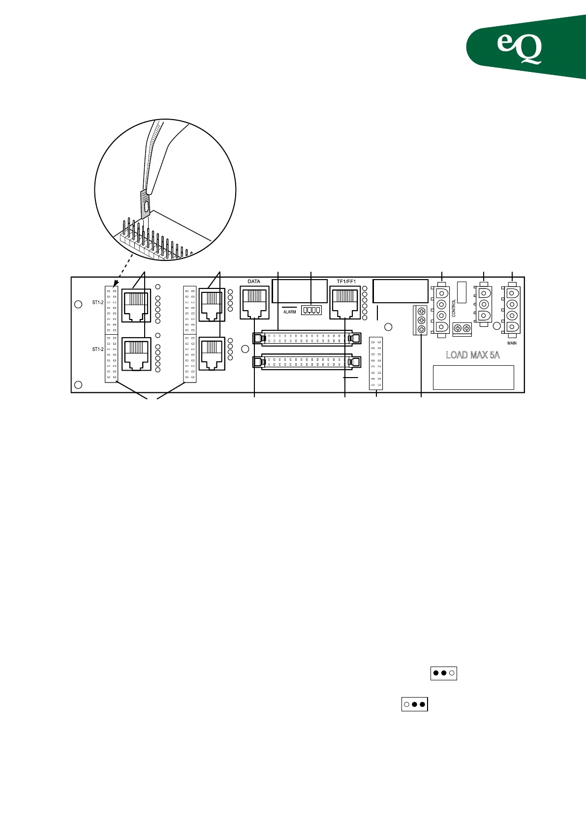
Connection board
Fig.11 Connect sensors and power supply through the cable trunking
On delivery factory tted control components are con-
nected to the distributed connection board. To obtain
signals to and from the control components jumpers must
be installed to the adjacent row of pins (pos. 6, 9 and 11).
These can be easily moved, using pliers for example
(see gure), to obtain a different function.
1. Constant power supply 230 VAC, max. 5A
•Rotaryheatexchanger
2. Control signal from relay, see also pos. 11 and 9
•Electricheater
•Cooler,heatpump
•Lighting
•Fanstart,highspeed
3. Signal distribution, incoming/outgoing including
the adjacent earth pin
4. Passive sensors and monitors
•GT7 Heatexchangerpressuremonitor
•GT3-4 Fan/owmonitors
•GT1-2 Filtermonitors
•GT12 Extractairsensor
•GT5 Frostprotectionsensor
•GT4 Temperature:coldcorner,exhaust
air, degree of efficiency supply air
•GT3 Outdoorairtemperature
•GT1 Supplyairtemperature
5. Control signals and active sensors
•GP5-6/GF1-2 Flowtransmitter(standard)
•GF1-2/L.TF/FF Flowtransmitter*
•ST1-2 Damperactuatoron/off
(including spring return mechanism)
•Mixing Modulatingdamperactuator
•BypassHEX Aux
•Recovery Heatexchanger
•Cooling Cooler
•Heating Electricheater,heatpump
6. Row of pins for selecting function on terminals 4 and 5
7. Internal communication bus
•Preheater
8. Signals to frequency converter, integral motor etc.
9. Row of pins for selecting digital functions
•AlarmTF/FF Alarmfrequencyconverter(pos.8)
•0VDC Aux
•24VDC Aux
•Lamp Lighting(pos.2)
•2-speed Highspeed(pos.2)
•StartTF/FF Directlystartedfan(pos.2)
•CP2/DX1 Cooler,heatpump(pos.2)
•CP1/EL Electricheater(pos.2)
10. Alarm
•Electricheater
•Cooler,heatpump
•Thermo-contacttrip/thermistor
11. Row of pins for selecting voltage pos. 2
•Servicepower Lighting
•L3Electricheaters,fanstart
cooler, heat pump
12. Incoming supply, control board: 230 VAC
* Alternative location of flow transmitters for air handling
units with pressure control and flow display.
ALARM TF/FF
0VDC
24VDC
LAMP
2-SPEED
START TF/FF
CP2/DX1
CP1/EL
GF1-2 SEC.
GP5-6/GF1-2
HEATING
COOLING
RECOVERY
BYPASS HEX
MIXING
GF1-2 SEC.
GP5-6/GF1-2
HEATING
COOLING
RECOVERY
BYPASS HEX
MIXING
GP3-4
GP1-2
GP7
GT1
GT3
GT4/11
GT5
GT12
GP3-4
GP1-2
GP7
GT1
GT3
GT4/11
GT5
GT12
LAMP
230VAC
CODE
CON.
GR1
GR2
L3´
L3
L N
J8003740 Ver. 2,0
1
1
4
3
2
1
4
3
2
1
4
3
6
5
2
1
6
6
1210345 12
9
7
8
6
11