20Fläkt Woods 8666 GB 2010.06
Specifications are subject to alteration without notice
Installation and maintenance instructions
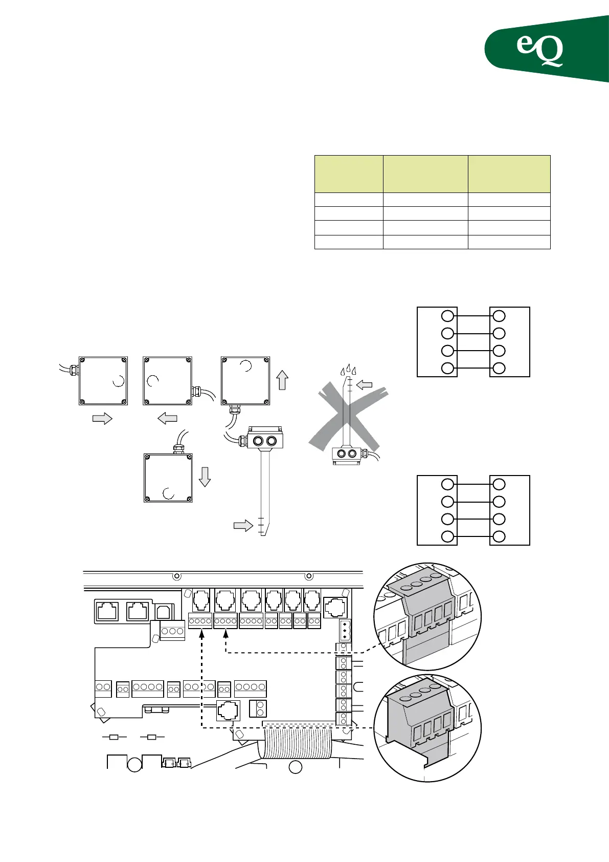
Control equipment
Terminal block Terminal block
in the in the control Signal
CO
2
-sensor panel (GP6/CO
2
)
G G 24 VAC (phase)
M G0 24 VAC (neutral)
U1 Y
Measurement signal
M M Measurement neutral
NOTE! To prevent a potential difference between the system
neutral and measurement neutral, route separate wires to
the appropriate sensors.
Fig.17
Permitted mounting positions for the duct sensor
Fig.18
Impermissible mounting positions
G G0 Y M
Z
G G0 Y M
GP6
CO
2
sensor
Supply 24 VAC, output signal 0-10 VDC, measurement
range CO
2
0-2000 ppm
The CO
2
-sensor is supplied as a separate accessory.
When installed in the duct position the sensor in the ex-
tract air duct as close to the air outlet as possible.
When installed in a room position the sensor where the
air quality is representative, for example, on an open wall
at a height of 1.5–3 metres. Connect the CO
2
-sensor to the
same input as the pressure sensor GP6; see the table for
CO
2
compensation. If the mixing damper is CO
2
control-
led connect the CO
2
sensor to the Z terminal block.
NOTE!
These cannot be connected at the same time!
GG
G0M
YU1
MM
CO
2
controlled fans
CO
2
sensor
eQ
terminal
GP6
GG
G0GO
YU1
MM
CO
2
controlled mixing section
CO
2
sensor
eQ
terminal
Z