Fläkt Woods 8666 GB 2010.06
Specifications are subject to alteration without notice
Installation and maintenance instructions
Control equipment
29
Frost protection sensor
Clamp on sensor: Ensure that the sensor element is in
con-tact with the pipe. Mount on the return pipe. Find a
representative location, scrape off any paint, apply paste
and position the sensor. Secure it well with the tension-
ing strap provided.
Immersion sensor: Install on the pipe rst in the air ow
direction. (Air drain pipe).
Permissible mounting methods
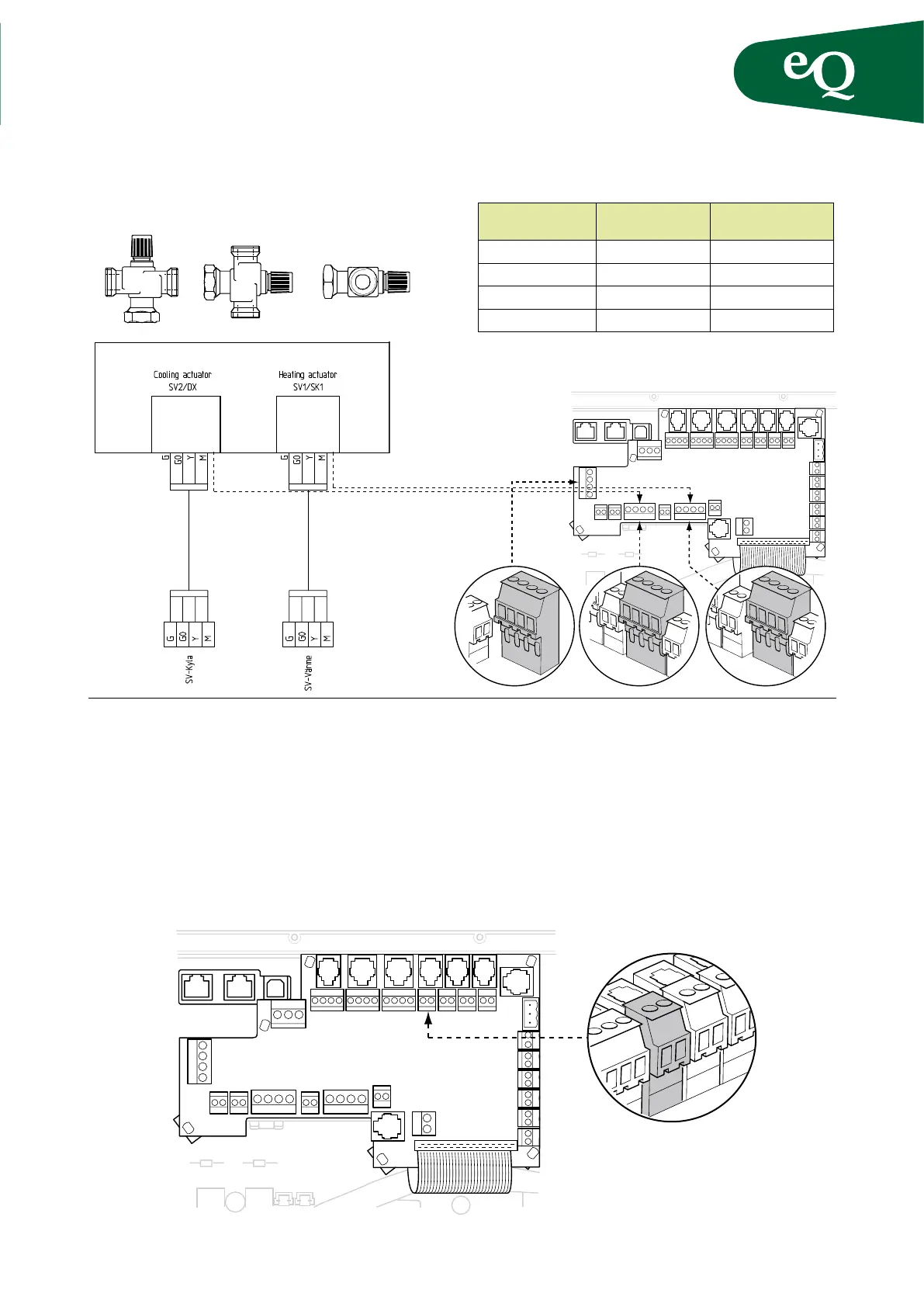
GT5
Terminal block:
Valve actuator
Terminal block:
Control panel
Signal
G G 24 VAC (phase)
G0 G0 24 VAC (neutral)
Y Y Control signal
G0 M Signal neutral
Applies to terminal blocks Cooling actuator,
Heating actuator and Control HEX.
Fig. 31
If the heating coil is located so far from the control cabi-
net that the cable does not reach, cut the connector and
splice the cable. Then connect it to screw terminal block
GT5. The wires are interchangeable.
G G0 Y M
SV1/SK1 0-10V
HEATING
ACTUATOR
G G0 Y M
SV2/DX
COOLING
ACTUATOR
G G0 Y M
CONTROL HEX
Fig. 30
Connection valve actuator