Fläkt Woods 8666 GB 2010.06
Specifications are subject to alteration without notice
Installation and maintenance instructions
Control equipment
19
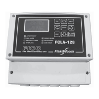
Nollställningsknapp
Byglar
1
2
3
4-20mA
ZERO
0,8/4s
Jumper 2
Jumper 3
24VDC
GND
0-10V
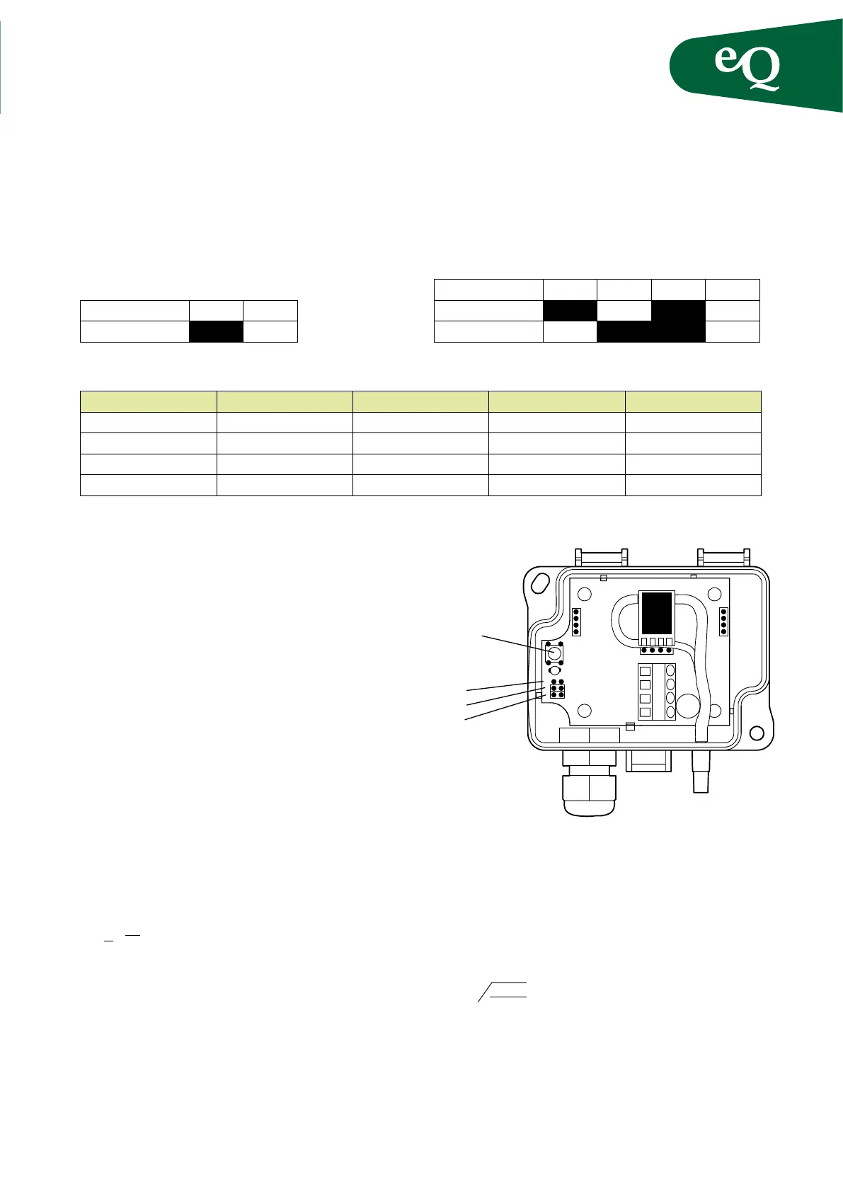
Configuration of the sensor
Where the pressure range must be changed on the sensor,
do this in accordance with the gures below.
Jumpers:
Response time 0,8s 4s
Jumper 1
Pressure range 1 2 3 4
Jumper 2
Jumper 3
NOTE!
A black field indicates a strapped connection.
Model Pressure range 1 Pressure range 2 Pressure range 3 Pressure range 4
DPT1000 –R4 250Pa 500 Pa 750 Pa 1000Pa
DPT3000 –R4 750Pa 1500Pa 2250Pa 3000Pa
DPT5000 –R4 1250Pa 2500Pa 3750Pa 5000Pa
DPT7000 –R4 1700Pa 3500Pa 5250Pa 7000Pa
NOTE!
The new pressure range must be entered into the controller when changing the pressure range on the sensor,
irrespective of whether the pressure or flow is being controlled. Read about this in the controller manual.
Zero point-calibration
NOTE! The sensors must be zero calibrated during commissioning.
They should then be zero calibrated annually.
The sensors should have been energized for approximate-
ly ve minutes before calibration is carried out. After that,
remove the hoses from the sensors. To start calibration,
press the button below the dip switches, see the gure.
Release the button when the LED lights.
Fig. 16
Zero point calibration
Flow determination according to the formula:
q
=
where the constant k is unique for each air handling unit
size. The k factor is shown on the air handling unit data
plate
k-factors
Dp m
3
/s
1
k
e
(273+t)
293
m
3
/s
e
Temperature correction
The ow scale on the display instrument and ow formula
above apply to air at a temperature of +20°C.
At other air temperatures the ow must be corrected using
the formula:
q = q
20
q = the true ow through the fan,
q
20
= the ow reading
t = current temperature in °C
Zero calibration button
Jumpers