18Fläkt Woods 8666 GB 2010.06
Specifications are subject to alteration without notice
Installation and maintenance instructions
Control equipment
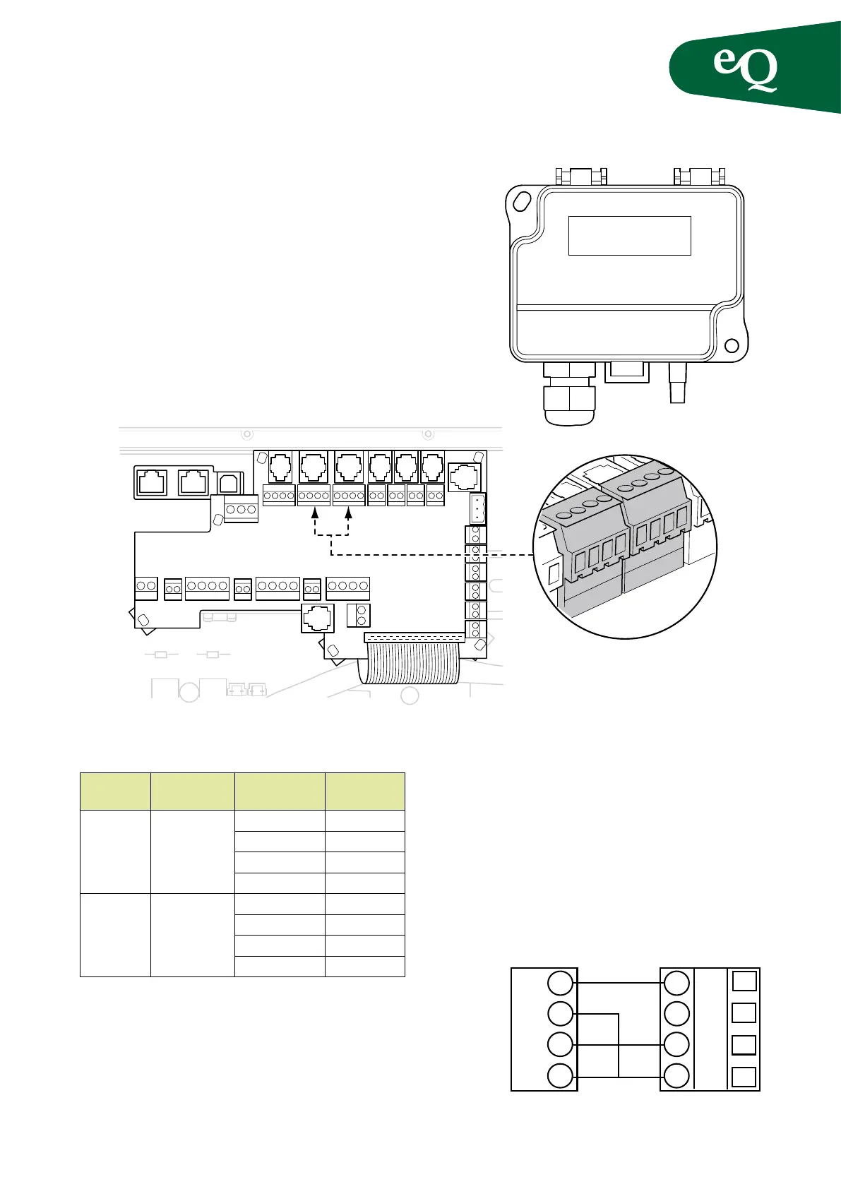
Pressure/flow sensor, DPT1000/3000/5000/7000
The pressure sensor is supplied as a separate accessory.
If pressure control is used, the air pressure in the index
duct is controlled (the duct with the highest pressure
drop and where the static pressure is the lowest). The rst
branch in the duct system is usually the index duct.
The pressure sensor is located at the beginning of this
duct. Position the extract air sensor, GP6, in an appropriate
position with a representative pressure in the extract air
duct. The ow sensors are always tted, even with pres-
sure control.
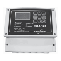
Location Terminal
block
Connection Pressure
sensor
Supply air
duct
GP5 Y 0-10V
M GND
G0 GND
G 24VDC
Extract
air duct
GP6 Y 0-10V
M GND
G0 GND
G 24VAC
Wiring (pressure control)
The pressure hose connected to the sensor must have an inner
diameter of 4 mm.
Flow control
The ow sensors are always installed, connected and
congured. The sensors are connected to the connection
board for each fan.
Pressure control, supply air with slave-
controlled extract air
The pressure sensor for the supply air is connected in the
same way as for pressure control, see above. The ow
sensors are always installed, connected and congured.
G G0 Y M
GP5
G G0 Y M
GP6
Fig. 13
Fig. 14
0-10V
4-20mA
24V
GND
Y
M
G
G0
Fig. 15
GP5/6 eQ terminal Pressure sensor