TemplateA4_v20130506
16
5.5 Component parts, equipment
Type
Température de service mini. / maxi. admissible
Surpression de service admissible
Surpression d`essai
Capacité nominale
N° de série
litres
bar
bar
Type
Typ
Serial-No.
Serien-Nr.
Nominal volume
Nenninhalt
Permissible working overpressure
Zulässiger Betriebsüberdruck
Test overpressure
Prüfüberdruck
Permissible working temperature min. / max.
Zulässige Betriebstemperatur min. / max.
litre
Liter
Flamco STAG GmbH
39307 Genthin
GERMANY
°C
:
:
:
:
:
:
:
:
:
:
:
:
:
:
:
:
:
:
Année de fabrication
Year of manufacture
Herstellungsjahr
:
:
:
1
1.1
1.2
1.3
1.4
1.5
1.6
1.7
1.8
1.9
1.10
2.2
2.3
2
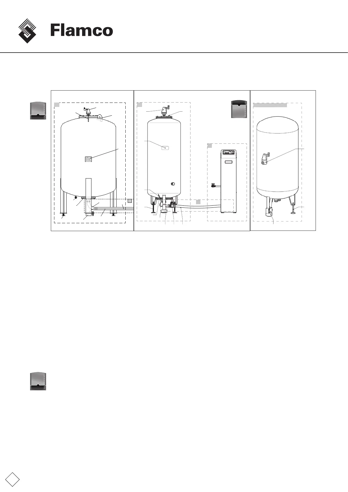
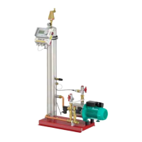
Fig. FM.017.V01.15
1A
1
1.1
3
2
1.5,
1.6
1.10
1.7
2.1
1.8
1.31.2
2.3 2.2
1000 Ltr
≤
1B
1C (Flamcomat starter)
1.2*
1.6
1.7
1 Basic steel vessel (1A/B with built-in,
exchangeable butyl-rubber diaphragm for
absorption of the expansion water under
atmospheric separation conditions).
1.1 Nameplate-Vessel:
1.2 Bleedervalve,oatventwith
air-intakepreventertodissipate
extractedgasesintotheatmosphere
*Incl.Vacuumsafetyvalve
1.3 Atmosphericpressurebalancingconnection
Interiorofvessel(spacebetweeninnervessel
surfaceandouterdiaphragmsurface)
1.5 Flange,vesselconnectionwithinternally
tteddegassingequipment,screw
union,connectionarray
valveoutowlineandpumpsuctionline,
eachwithatgasket(labelling)
1.6 Adjustablefeet.
1.7 Capacitysensorwithscrew-typeround
plugconnectortosignalwire
1.8 Signalwirelevelsensor
1.10 Markingsforpumpandvalveconnection
1.4 Liftinghook,loadsuspensionfortransport
1.9 Lockshieldvalveforcondensatedrainage
2 Connection assembly, pre-installed, including
at seal
2.1 Self-draininglockshieldvalve(vessel)withat
seal,controlunitport
2.2 Flexiblepressure/suctionhose
2.3 Pipebend,atsealing,vesselconnector(DN32:
400 - 1000 liter, DN40: 1200 - 1600 liter.)
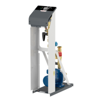
3 Pump module, control module, including type
plate
3.1 Pumppressurepipe,systemsupply(marking)
3.2 Pressure sensor
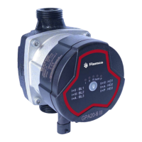
3.3 Pump 1 with manual de-aeration
(hexscrewwithseal)
3.4 Pump 2 with manual de-aeration
(hexscrewwithseal)
3.5 Pump1,wetrunner,self-priming
Aspeedselectswitch,max. position!
BVent(slotted-headscrewwithseal)
3.6 Pump2,wetrunner,self-priming
Aspeedselectswitch,max. position!
BVent(slotted-headscrewwithseal)
3.7 Valvedischargepipe,systemdischarge(marking)
3.8 Particlelter
3.9 Non-returnvalve
3.10 Manualregulatedvalve1(diagram)
3.11 Manualregulatedvalve2(diagram)
3.12 Solenoidvalve,overowvalveno.1
3.13 Solenoidvalve,overowvalveno.2
3.14 Top-upline,incorporatingtheshut-offvalve
(lockshieldvalve),exiblepressurehose,solenoid
valve,top-upvale,no.3,andcheckvalve
(optional)
3.16Safetyvalve(vessel)
3.17Lockshieldvalvesystemconnection(optional)
3.18Automaticdeaeratorwithair-intakepreventer
(MP,DP60-1-50)
3.19 Controlunit,SPCx-lwincludingtypeplate
3.20 Controlunit,SPCx-hwincludingtypeplate
3.21 Bleedpump
3.22 Front panel
3.23 Manualregulatedvalve3(diagram)
1000 Ltr
>
1000 Ltr
>