TemplateA4_v20130506
22
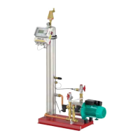
6. Assembly
6.1 Setup
A/B C
(Flamcomat starter)
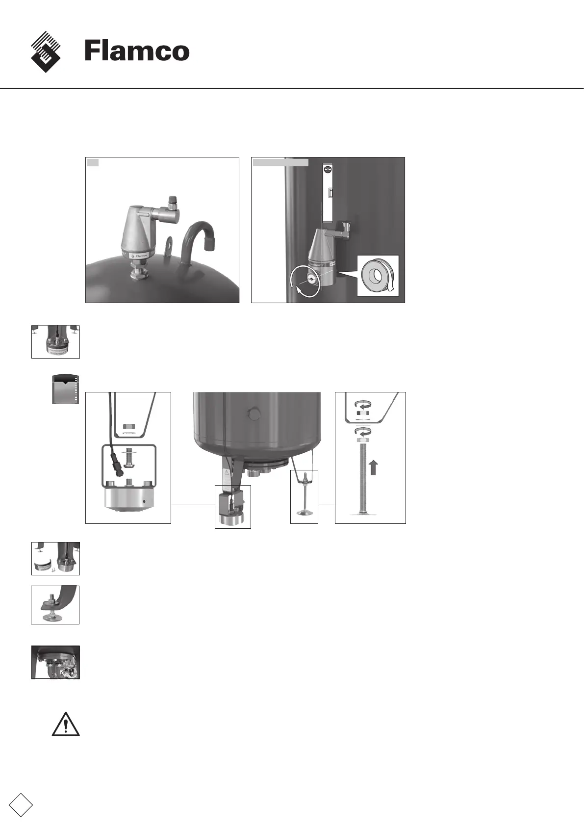
• Fittheautomaticvent(suppliedseparately).
• Removethetransportsealbythevolumesensoroncethebasicvesselhasbeensetupintheproposedplaceandnofurther
positionalchangesarenecessary.Avoidimpactonthesensorandmakesurethesensorisonasurfacewhichdoesnotimpair
thefunctionofthesensorpressure-pad.
• Installationoftheweight-capacitysensorandtheadjustablefeet.
• Usingthefoot-heightadjuster,adjustthevesseluntilitisvertical.Usetwoverticalmagneticspiritlevels.
• Ensurethatnoexternaladditionalforcescanbeexertedonthebasicvessel(e.g.toolslaidonthevessel,thingsleaningonthe
sides).
• Donotxthebasicvesseltothegroundonwhichitiserected(donotuseanysortoffasteningwhichcanadverselyaffectthe
vessel,e.g.sinkingthefeetintoconcreteorlime,weldingofthevesseloritsfeet,clampsandtiesonthebodyofthestructure
orappurtenances).
• Placethecontrolmodule,thebasicvesselandtheauxiliaryvesselatthesameheight.
6.2 Vessel connection
Thevesselconnectionisproducedasanelectricorhydraulicconnectiontothepumpmodule.Fortheinstallationdiagram
andexampleinstallationseeappendix1.Pleaseobservethefollowingpointspriortollingandcommissioningofthepressure
expansionvessels:
• Installtheconnectionassemblybetweenthevesselandthecontrolmodule.
Caution:Ensurethattheconnectionbetweenthepumpmoduleandthebasicvesselismadewiththesuppliedexiblepressure
hoses(connectionassembly).
Fig. FM.030.V01.15
1000 Ltr
≤
Fig. FM.031.V01.15
Fig. FM.032.V01.15
Fig. FM.033.V01.15