TemplateA4_v20130506
23
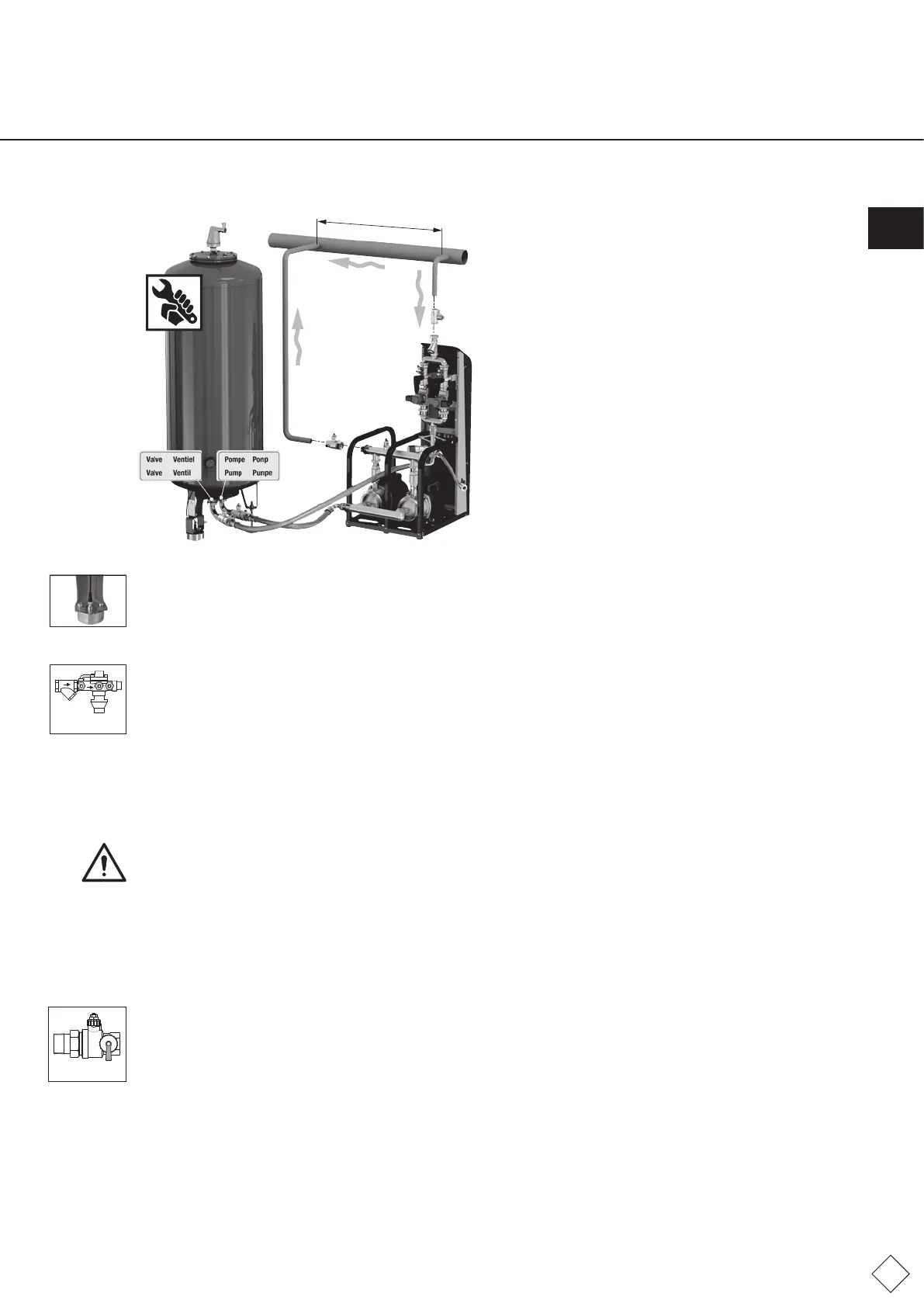
Takenoteofthelabels‘pump’and‘valve’ontheconnectionsand
connectuptheappropriateconnectionfromthepumpmodule
(valve)tothepump(valve)onthevesselconnection.
Donotcrosstheseconnectionsand,ifnecessary,mountthe
vesselconnectionangesoastoenableparallelpipetting.Use
theatsealssupplied.
• Connectthesignallineviathequick-releaseconnectiontothecapacitysensor.Screwthisconnectionentirelyintothe
connector(protectionclassIP67).
• Openthelockshieldvalveontheconnectionassemblybetweenthevessel(basicvessel,intermediatevessel)andcontrolmodule.
6.3 Top-up connection
Thetop-upconnectionshouldbeconnectedtothecontrolunit.Assuredtop-uprequiresanaveragesetfeedpressureof
approx.4-6bar(max.8bar).Highfeedpressuresmayrequiredevicestopreventwaterhammer(pressurereducingvalve).
Appendix 1 shows the installation diagram and example installation.
Pleaseobservethefollowingspecicationsbeforellingandcommissioningthepressure-expansionautomat:
• Installthefeedtothetop-uphosewithshut-offvalve(asdelivered).
• Avoidanytensileloadsonthehose,bendingradiioflessthan50mmandcontractions.
• Ifthetop-upfeedisconnectedtothewatermain,abackowpreventerwithltermustbeconnectedinseriesincompliance
withEN806-4/EN1717.Installthisaccessoryhorizontallyandtashut-offvalvebeforethisassembly(note:cleanlter
regularlyandchangeltersasandwhenrequired).
Caution:Connecttheshut-offvalvetothetop-upintake.
6.4 Drain connection
Tosafelyroutethevolumeowstobedischargedatthesafetyvalve(Pos.3.16),backowpreventer(accessory,top-up)andthe
atmosphericpressurecompensationconnection(Pos.1.3)adrainisrequiredinthevicinityoftheFlamcomatequipment.
• Installadrainfunneland,ifnecessary,adrainpipeforthebackowpreventer.
• Whenadischargepipeisconnectedtothesafetyvalve,theconnectionmustbekeptopentoatmosphericpressure.An
atmosphericfunnelfromtheFlamcoproductcataloguecanbettedforthispurpose.
6.5 System connection
Thesystemconnectionshouldbeconnectedtotheheatingorcoolingsystem.
Appendix 1 shows the installation diagram and example installation.
Pleaseobservethefollowingspecicationsbeforellingandcommissioningthepressure-expansionautomat:
• Theconnectionshouldpreferablybemadeinthereturnlineoftheheatingsystem.Pleasenotethatatemperatureatthe
systemconnection>70°C(...80°C)wouldexceedthepermissiblepump/diaphragmloadandpossiblyleadtodamage
tocomponents.(Completeinsulationoftheexpansionpipemayincreasethetemperatureloadonthecontrolunitandthe
diaphragm).
• Makesurethatthisconnectionisdirectlyconnectedtotheheatgenerator,andthattherearenoexternalhydraulicpressure
inuencespresentatthepointofentrainment(e.g.hydraulicbalancers,distributors).
• Theowdetermineshowyoushouldinstalltheexpansionlines.Whenttingexpansionlinestothereturn>5minlength,use
pipesofatleastonenominaldiameterlargerthanthatofthepumpmodule.Avoidadditionalloadstothesystemconnectionof
thecontrolunit(e.g.fromheatexpansion,owoscillations,deadweights).
• Equipmentwithowtemperatures>100°Cmusthaveaminimumpressurelimiterttedintheexpansionline(systemdrain,
valvedrainpipework).ThearrangementiscontainedinAppendix1.InapplicationsinaccordancewithDINEN12828:2003(D),
thislimiterisonlyenvisagedforuseifthepressureholdingdevicedoesnothaveanautomatictop-upsystem.
>1 m - < 2 m
Fig. FM.034.V01.15
Non-returnvalve
Fig. FM.035.V01.15
Lockshieldvalve
Fig. FM.036.V01.15
ENG