TemplateA4_v20130506
20
2
4
1
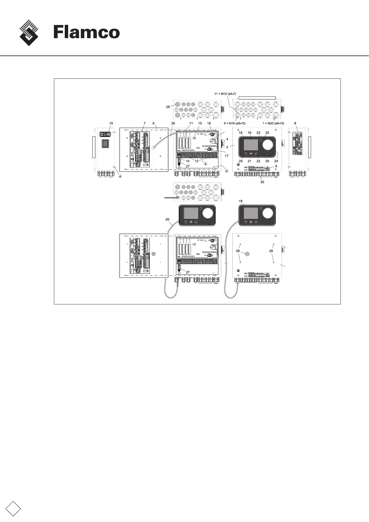
Screw-typecableconnectors,
Standardequipmentlevel
SPCx-lw
Fig. FM.026.V01.15
Screw-typecableconnectors,
Maximumequipmentlevel
1 Control unit SPCx
2 Control unit SPCx-lw
3 Control unit SPCx-hw
4 MainpowerswitchL,N;On:“Redlight”
5 MainpowerswitchL1,L2,L3,N;
On:”Display,Pos.19;LED,Pos.15On”
6 Controlunitcoveropen,insideview
7 Terminalportdiagram(seeterminalplan)
8 Control unit name plate
9 Electricalwarnings
10 Serviceconnectioninformation
11 Slots,slot1...4(SPCextension,option)(openingsto
accommodatemodulesviapredeterminedbreaking
points)
12 ScrewterminalsI/Oports
(seeSPCx-lwterminalplan)
13 ScrewterminalsI/Oports
(seeSPCx-hwterminalplan)
14 RS485serialportconnector
(Dataprotocol,optional)
15 LEDwarninglights,backlit*
LED,yellowon: Automaticmodeoff;controllerisin
congurationmodeorcommissioning
menunotcompleted.
LED,greenon: Theterminalison;theSPCis
connectedtotheSPCterminal
LED,redon: systemerror,identicaltopos.23
16 MicrofuseF1;16AT;equipmentprotection
17 MicrofuseF2;400mAT;additionalequipment
protection;
valve1;1.1;2;(outputportno.:42;43/45;46/48;49)
18 SPCTerminal(displayandoperatingpanel)
19 Graphicdisplaywithbacklight
(dimmerinenergy-savingmode)
20 Sensorbutton:“Back”orfunctionsasshown
in the display.
21 Sensorbutton,unlockthekeyfunctionsforbacklighting
(blue).Backlightingandfunctionalassignmentsalso
shown in the display.
22 Sensorbutton:“Conrmed...Enter”
23 Sensorbutton:“Errorcall”
24 Sensorslider,selector
25 Backlightonwhenkeyfunctionisready.Alsofunction
forunlockingthebuttons
26 SPC terminal feed wire
27 RS232port,SPCterminal
28 Capplugs,SPCterminalmountingholes
29 Plugs,locationhole
cableglands
30 Screw-typecableconnectors
31 Motor1motorcircuitswitchcombination
(MPversions:SPCx-hw-1-1and-2)
32 Motor2motorcircuitswitchcombination
(DPversions:SPCx-hw-1-2)
* additional displays (analysis).