TemplateA4_v20130506
38
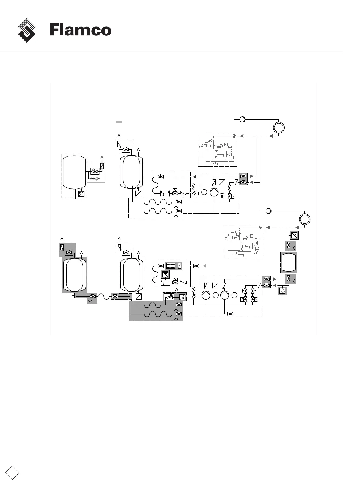
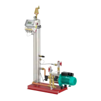
Installation examples
P
M1
E
V1
E
F
m
3
V3
T
T
P
P
P
P
M2M1
E
T
V1 V2
m
3
V3
V
E
F
P
T
T
P
P
Mainvessel
Flexibleconnectiongroup
(Top-upfeed
non-potablewater)
Control module MP
Lockshieldvalve**
Heatgenerator
System
intake
System
output
Supplytemperature<=105°C
(STB<=110°C)
Return temperature
<=70°C
VesselconnectorBB**
Auxiliaryvessel(BB)**
3)
Lockshieldvalve
with draining **
T-pieceG11/2"
vesselbranch**
Sensorconnectiongroup**
Control module DP
Temperature sensor **
Hose
3)
G11/2"
Backowpreventer**
(top-upfeedpotablewater)
Impulse water meter **
Heatgenerator
Supplytemperature>105°C
1)
Return temperature
<70°C
Minimum
pressure
limiter **
2)
Lockshieldvalve
with draining **
Fig. FM.041.V01.15
Mainvessel
Flamcomatstarter
Distancesystemsupply,
systemdischarge,atreturn
integrationpoint,intherange
0.5 ... 1 ... m.
Pleasenote:Ifthereturnline
isroutedhorizontally,donot
implementtheconnection
frombelowtoavoidadditional
contaminationwithdirt.
1)
Fordesigntemperatures>100°Cand>110°C,additional
requirementsfromapplicableEuropeanstandardsmayapply.
2)
Notrequiredacc.toDINEN12828
3)
Addadditionalauxiliaryvesselssymmetricallyusingacollectorline
(mainvesselatcentre)takingintoaccountminimumdistances.
Thebranchfromthemainvesselmustbeexible.
**accessory,optionalextra