Introduction
5
5.1 Example system overviews
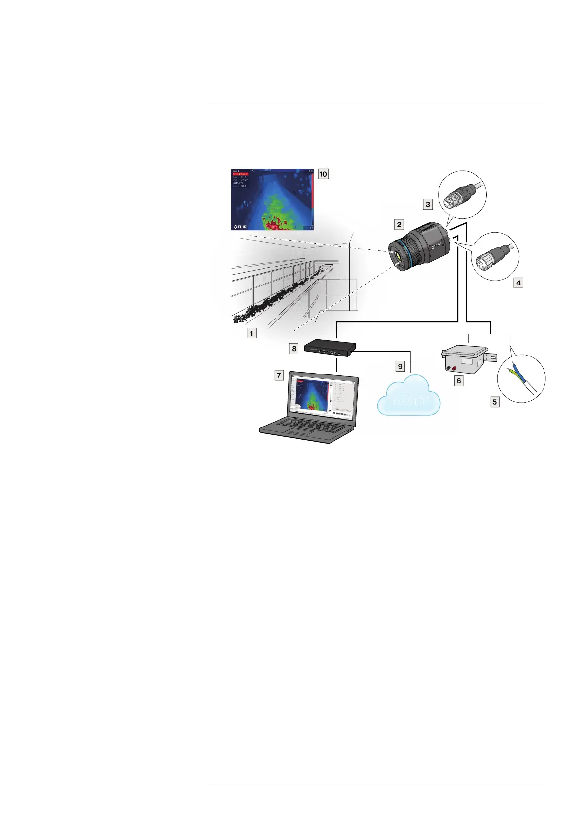
5.1.1 Early fire detection
Figure 5.1 Hot spot detection, self-combustible material on conveyor belt
1. Coal mine conveyor belt.
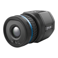
2. FLIR A400/A500/A700 Smart Sensor camera.
3. Ethernet connector, X-coded.
4. Power I/O connector, A-coded.
5. Digital output to a programmable logic controller (PLC).
6. Separate DIN rail power supply for galvanic isolation (18–56 V DC).
7. Laptop used for set up of the camera using the web interface.
8. Ethernet switch.
9. MQTToutput connected to a third-party cloud service.
10. Example thermal image.
#T810409; r. AH/78915/78915; en-US
8
 Loading...