Home
FLIR
Thermal cameras
A500 Series
FLIR A500 Series User Manual
5
of 1
of 1 rating
69 pages
Give review
Manual
Specs
To Next Page
To Next Page
To Previous Page
To Previous Page
Loading...
A-series
connection
board
12
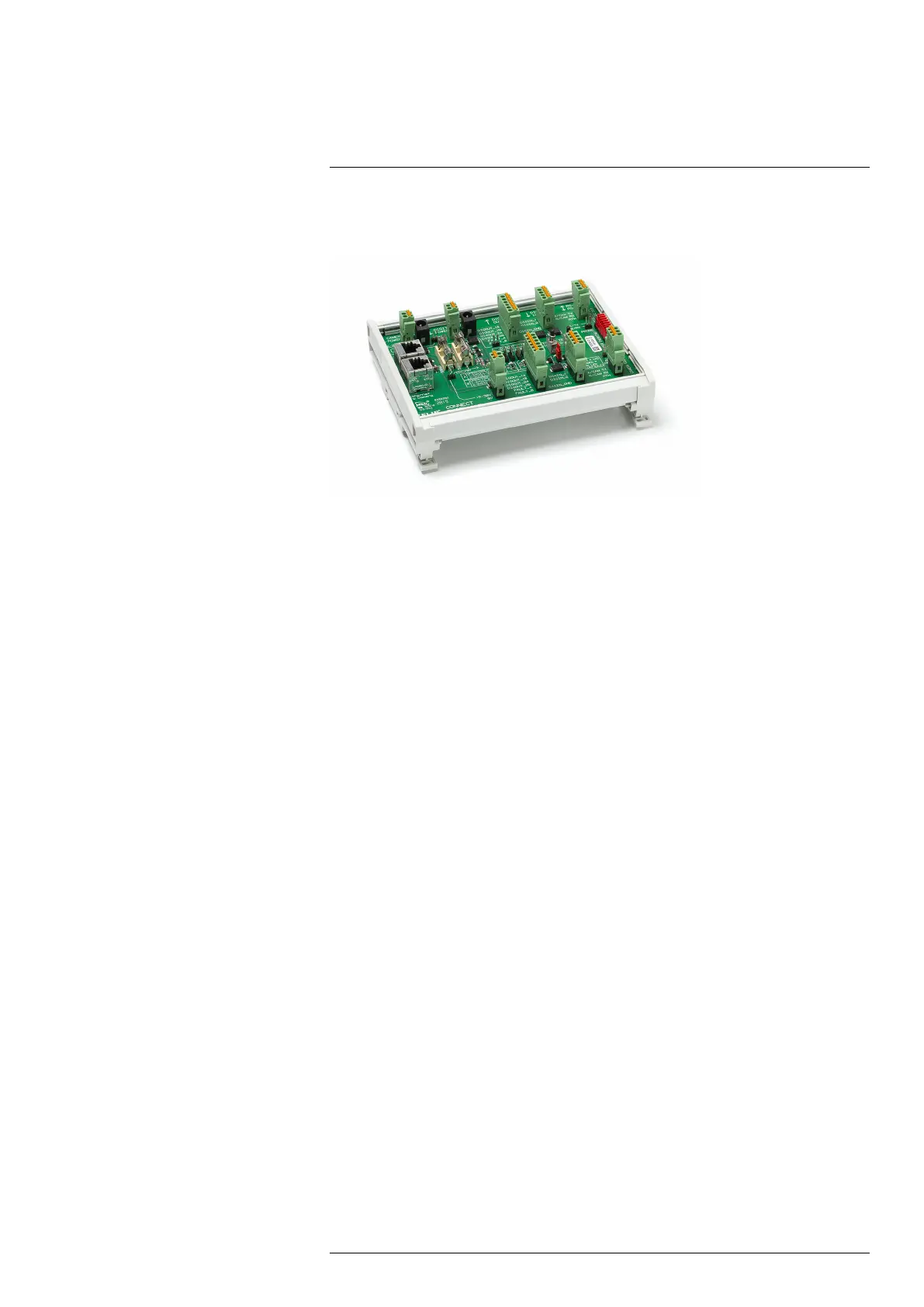
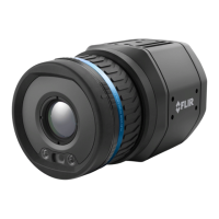
The
A-series
connection
board
is
an
accessory
that
can
be
used
to
test
functionality
and
digital
connections
to/from
the
camera.
Figure
12.1
A-series
connection
board
For
schematics
and
connection
ex
amples,
see
the
next
pages.
#T810409;
r.
AH/78915/78915;
en-US
42
45
47
Table of Contents
Table of Contents
3
Disclaimers
5
Legal Disclaimer
5
Government Regulations
5
Patents
5
Quality Assurance
5
Third-Party Licenses
5
Usage Statistics
5
Copyright
5
Safety Information
6
Notice to User
8
Register Your Camera
8
Calibration
8
Accuracy
8
Disposal of Electronic Waste
8
Training
8
Documentation Updates
9
Important Note about this Manual
9
Note about Authoritative Versions
9
Customer Help
10
General
10
Submitting a Question
10
Downloads
10
Introduction
11
Example System Overviews
12
Early Fire Detection
12
Quality Assurance
14
Condition Monitoring
15
Research & Development
16
Camera Parts
17
Camera Installation
18
Mechanical Installation
19
RTSP Streams
20
Camera Web Interface
21
Supported Browsers
21
Login
21
Navigation
21
Camera Tab
22
Working with Measurement Tools
22
Working with Alarms
26
Changing Object Parameters
28
Working with Image Modes
29
Colorizing the Image
30
Auto-Adjust Region
32
Calibrating the Camera
32
Using the Camera Lamp
33
Changing the Temperature Range
33
Adjusting the Temperature Scale
33
Flipping the Image
34
Full Screen View
34
Saving a Snapshot
34
Pausing the Live Image Stream
35
Hiding the Overlay Graphics
35
Camera Presets
35
Administration Tab
35
Firewall
35
SSL Certificates
35
Services
35
Web Protocols
36
User Management
36
Regional Settings
36
Network Settings
37
System and Firmware
37
SNMP Settings
38
Multicast Settings
38
Settings Tab
38
General Settings
38
Alarm Recipients
39
Scheduler
39
Mqtt
40
Modbus
40
Library Tab
41
Managing Images
41
Managing Videos
41
Managing Logs
42
Pin Configurations
43
Ethernet Connector and Cable
43
Power/Digital I/O Connector and Cable
44
RS232/RS485 Connector
45
Series Connection Board
46
Connection Examples
48
Software Supported by FLIR A400/A500/A700 Series Cameras
54
Mechanical Drawings
55
EU Declaration of Conformity
59
Indicator Leds and Factory Reset Button
61
Power/Error Indicator LED and Factory Reset Button
61
Power/Error Indicator LED and Power Modes
61
Wired Ethernet Connection
61
Cleaning the Camera
62
Camera Housing, Cables, and Other Items
62
Infrared Lens
62
About Calibration
63
Introduction
63
Definition-What Is Calibration
63
Camera Calibration at FLIR Systems
63
The Differences between a Calibration Performed by a User and that Performed Directly at FLIR Systems
64
Calibration, Verification and Adjustment
64
Non-Uniformity Correction
65
Thermal Image Adjustment (Thermal Tuning)
65
About FLIR Systems
66
More than Just an Infrared Camera
67
Sharing Our Knowledge
67
Supporting Our Customers
68
5
Based on 1 rating
Ask a question
Give review
Questions and Answers:
Need help?
Do you have a question about the FLIR A500 Series and is the answer not in the manual?
Ask a question
FLIR A500 Series Specifications
General
Brand
FLIR
Model
A500 Series
Category
Thermal cameras
Language
English
Related product manuals
FLIR ADK
27 pages
FLIR A65
156 pages
FLIR A15
156 pages
FLIR A615
124 pages
FLIR A655sc
124 pages
FLIR A6 Series
124 pages
FLIR A700 Series
67 pages
FLIR Vue
2 pages
FLIR ONE
15 pages
FLIR E96
115 pages
FLIR M400
60 pages
FLIR Scout
38 pages