x
List of Figures
Figure Title Page
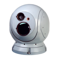
1-1 SeaFLIR II Imaging System Units...................................................4
1-2 Laser Aperture Label ......................................................................9
1-3 Laser Interlock Safety Label ...........................................................9
1-4 Laser Safety Switch (Key controlled)..............................................10
2-1 System Interconnect Diagram ........................................................14
3-1 Hand Control Unit ............................................................................16
3-2 Graphic Symbols.............................................................................20
3-3 SHIFT Display.................................................................................23
3-4 Non-Uniformity Correction (NUC) Display ......................................26
3-5 IR Camera Non-Uniformity Correction (NUC).................................26
3-6 White Hot Polarity Display ..............................................................28
3-7 Black Hot Polarity Display...............................................................28
3-8 Auto Scan Width Adjust Display .....................................................30
3-9 Top Level Menu ..............................................................................31
3-10 Initial Setup Menu .........................................................................33
3-11 Symbology Level Select Menu .....................................................35
3-12 Platform Symbol Select Menu ......................................................37
3-13 None Platform Symbol..................................................................37
3-14 Ship Platform Symbol ...................................................................37
3-15 Helicopter Platform Symbol ..........................................................37
3-16 Fixed Wing Platform Symbol ........................................................37
3-17 SGA Platform Orientation Select ..................................................38
3-18 Hardware configuration Menu.......................................................39
3-19 GPS Device Select Menu .............................................................40
3-20 GPS Device Selected (No GPS Data) ..........................................41
3-21 GPS Data Display .........................................................................41
3-22 Stale GPS Data Display................................................................41
3-23 NMEA (Radar) Select Menu .........................................................42
3-24 Radar Configuration Menu............................................................42
3-25 Baud Rate Select Menu ................................................................43
3-26 RBH Elevation Select Menu .........................................................43
3-27 Color scheme Select Menu...........................................................44
3-28 Color Schemes .............................................................................45
3-29 System Power Switch ...................................................................46
3-30 System Startup Standby Display ..................................................46
3-31 Agency Name Setup and Edit Display..........................................49
3-32 Date and Time Setup and Edit Display.........................................50
3-33 Radar Off-Line Display..................................................................56
3-34 Radar Bearing Invalid Data Display..............................................57
3-35 Radar Bearing Single Shot Mode Display ....................................58
Commercial in Confidence
Export Level 2
Issued to: AgustaWestland
CM Ref:4049
Valid on Day of Issue only.
Document will not be updated
Uncontrolled : 4256
Retrieval Date:07-Dec-10
Requested by Bower, Richard
 Loading...