58
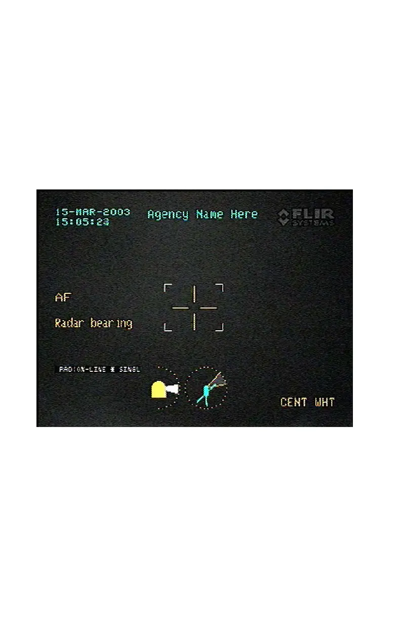
displayed in the lower left side of the video display (Figure 3-36). The
operator can offset (fine tune) the radar input with the Strain Gauge to
center the target in the display. An offset indicator (left , right , up ,
or down ) will appear to the right when the offset (either axis) is greater
than 2. Use of the SYM Switch during Radar Bearing Continuous Mode
will remove any offsets and center the SeaFLIR II on the radar pointing
position. The azimuth and elevation offsets introduced by the operator
will be maintained. Once the operator decides to use the SeaFLIR II
Auto-tracker, it will override the Radar Bearing Mode and attempt to track
the target. If the SeaFLIR II tracked target is lost, the system will return
to Radar Bearing Mode.
Figure 3-35. Radar Bearing Single Shot Mode Display
Commercial in Confidence
Export Level 2
Issued to: AgustaWestland
CM Ref:4049
Valid on Day of Issue only.
Document will not be updated
Uncontrolled : 4256
Retrieval Date:07-Dec-10
Requested by Bower, Richard
 Loading...