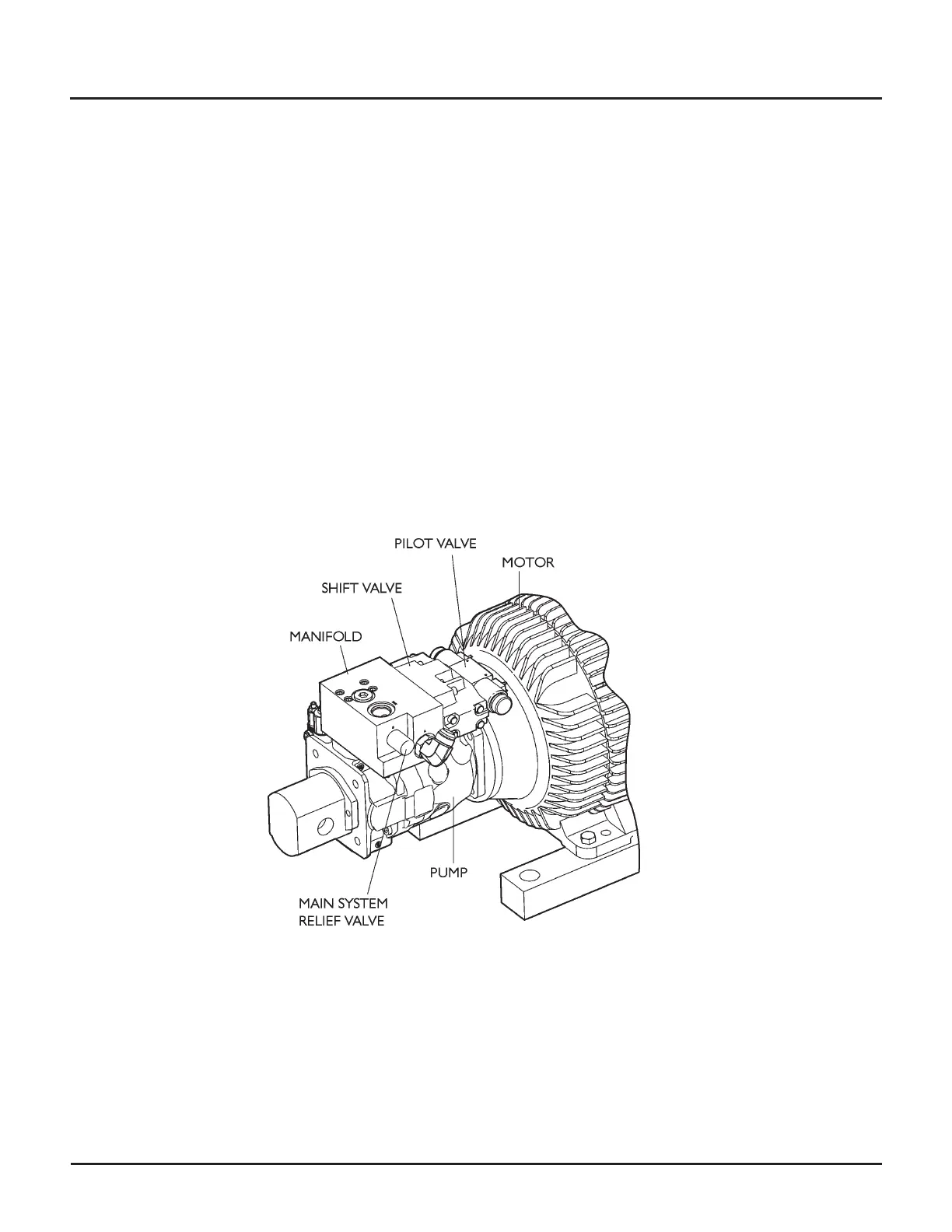
Servicing the shift valve manifold assembly
Each manifold assembly contains the following
components:
•
Pilot valve
•
Shift valve
•
Main system relief valve
•
Manifold body
This section contains service procedures for these com
-
ponents. Intensifier service procedures are located in
your intensifier manual.
The manifold assembly and its component parts require
no routine maintenance.
All operations require the reservoir to be drained.
How it works
Hydraulic oil is supplied at pressure to the manifold
body from the associated main hydraulic pump. The
shift valve distributes the flow of oil through the mani
-
fold to each end of the intensifier low-pressure cylinder
in turn, as required. The shift valve directs the return
flow of oil from the other end of the intensifier to the
reservoir via the return port of the manifold at the same
time.
The shift valve is operated hydraulically by a pilot valve
mounted above it. The pilot valve is operated by two
solenoid coils controlled by the integrated shift module.
This module receives its timing signals from the shift
sensor assemblies in the intensifier end bells, which di
-
rectly sense the presence of the intensifier piston as it
comes to the end of its stroke at each end bell in turn.
58 | M-390 © Flow International Corporation
HYPERJET™ 94i-S AND 94i-D PUMPS