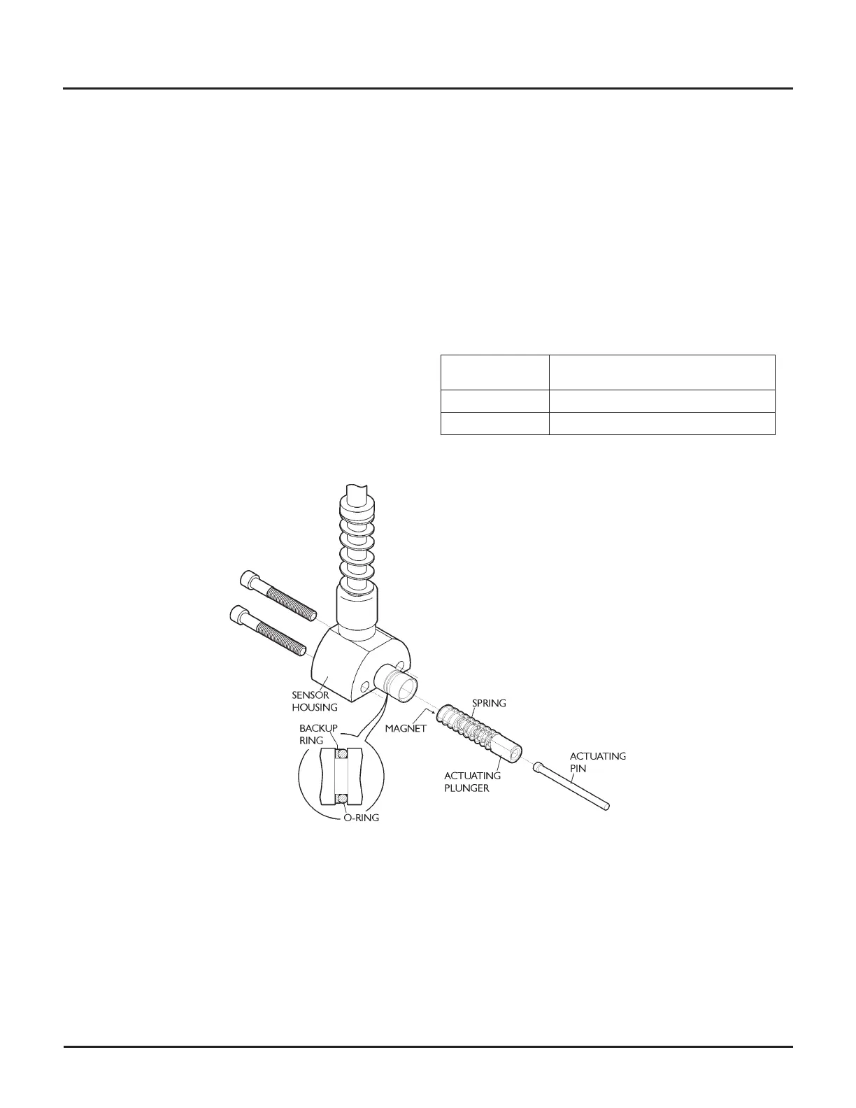
Shift sensor assembly
The shift sensor assembly consists of an actuating pin,
actuating plunger assembly, spring, sensor housing and
two cap screws. The assembly requires no routine
maintenance.
How it works
As the intensifier low-pressure piston nears the end of
its stroke, it pushes on the actuating pin. The actuating
pin pushes on the actuating plunger and spring, which
brings the magnet end into the cupped end of the sen
-
sor housing. The magnetic field causes the sensor to
send a signal to the integrated shift module, which en
-
ergizes the appropriate pilot valve solenoid coil. This
causes the intensifier to stroke in the opposite direction.
See Integrated shift module for a description of the
module indicator LED sequence of operation.
Service tips
The most common shift sensor problems are:
•
Leakage due to a worn o-ring
•
A stalled or erratically shifting intensifier caused by a
broken spring
•
A stalled intensifier caused by a break in the wiring.
To check the shift sensor wiring, stand in front of the
pump.
The shift sensor electrical connections are as
follows:
Connector
location
Connects to
Bottom left Left-hand shift sensor
Bottom right Right-hand shift sensor
© Flow International Corporation M-390 | 67
CHAPTER 5
Servicing the Pump