Integrated shift module
The integrated shift module is mounted in the pump’s
front panel. The electronics board is permanently sealed
in the module to prevent damage and is not a service
-
able component.
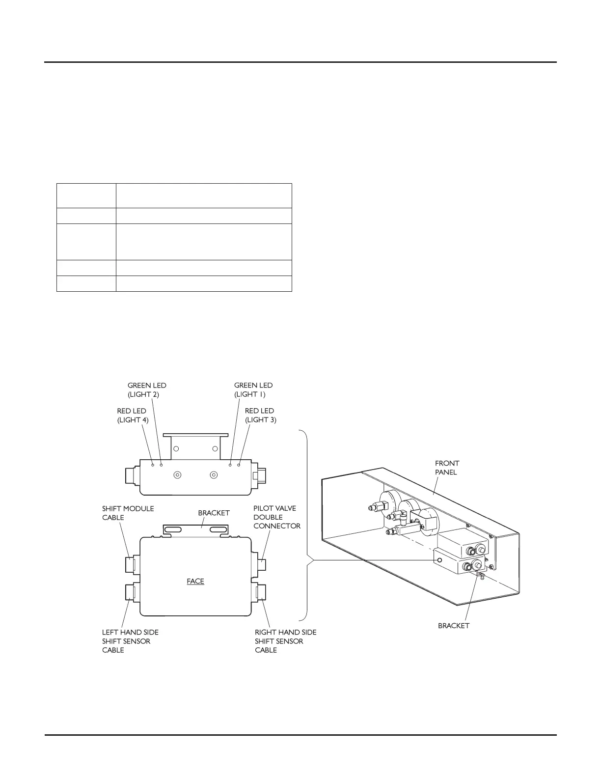
When viewed from the face with the bracket, with the
bracket up, the electrical connections are as follows:
Connector
location
Connects to
Top left Shift module cable
Top right Pilot valve solenoid coils double connector
cable (cable is on the right-hand side of the
pilot valve)
Bottom left Left hand side shift sensor cable
Bottom right Right hand side shift sensor cable
LED indicator lights on the top of the module indicate
the operation of the circuit.
•
A green LED lights up when the shift sensor on the
same side is energized by the intensifier piston
•
A red LED lights up when the pilot valve solenoid
coil on the same side is energized
CAUTION
At no time should both LEDs of the same color be lit.
If both red LEDs are lit together, there is an internal fault
in the module and it must be replaced. If both green LEDs
are lit together, there may be an internal fault in the
module or a fault with either shift sensor assembly.
See Shift sensor assembly for instructions.
Use the troubleshooting tips in Shift sensor assembly to
identify whether a shifting problem exists in the sensor
assemblies or in the shift module. If both shift sensor as
-
semblies are known to be working correctly, there is an
internal fault in the module and it must be replaced.
60 | M-390 © Flow International Corporation
HYPERJET™ 94i-S AND 94i-D PUMPS