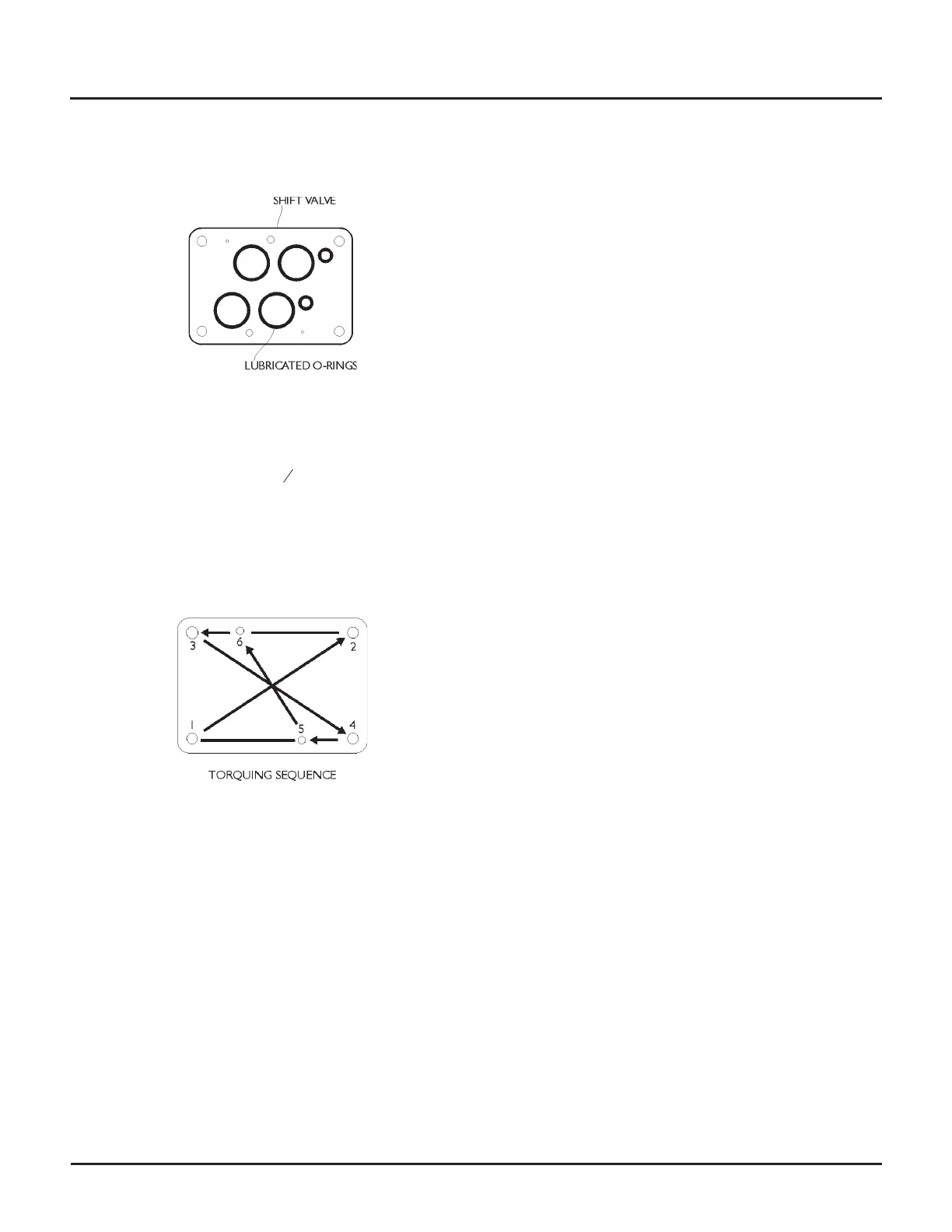
7. Inspect the o-rings for wear and replace as
necessary. Lubricate the o-rings with Parker Super O
Ring Lube and insert them in the shift valve.
8. Place the shift valve body on the manifold so that
the offset ports in the shift valve match those in the
manifold. Thread in the cap screws.
9. Torque the cap screws in
1
8
-turn increments in this
two step process:
a. Torque all cap screws (in the order 1 to 6, as
shown) to 11.5 ft-lb (15.6 N-m).
b. Torque the outer cap screws (in the order 1 to 4,
as shown) to 55 ft-lb (74.5 N-m).
10. Use your fingers to make sure the spool moves
freely.
11. Lubricate the end cap o-rings with Parker Super O
Ring Lube and install in the end caps. Install the end
caps on the shift valve body. Torque the cap screws
to 30 ft-lb (40.7 N-m).
12. Install the pilot valve (see Pilot valve).
Note: If the reservoir was drained in Step 1, refill
the reservoir.
13. Remove the Out of Service tags from the main elec
-
trical disconnects.
Note: This service procedure introduces a small
amount of air into the hydraulic system, which will
purge automatically on pump unit start-up.
14. Run the pump unit at low pressure for 3–5 minutes
while checking for leaks. Remove tools, parts and
rags from the pump unit.
The pump unit is ready for operation.
© Flow International Corporation M-390 | 65
CHAPTER 5
Servicing the Pump