FW_F115-P_M_v2201-01_EN.docx
4.5.5 SENSOR SUPPLY
For type PB / PX Terminals 11 and 14: Limited sensor supply
These types of power supply only offer a limited sensor supply, which SHOULD NOT be used to
supply the flowmeters electronics, converters etc. as it will not provide adequate sustained power!
All energy used by the flowmeters pick-up will directly influence the battery life-time. It is strongly
advised to use a "zero power" pickup such as a coil or reed-switch when operating without external
power. It is possible to use some low power NPN or PNP output signals, but the battery life time will
be significantly reduced (consult your distributor). The sensor supply is fixed to 1.2V for coil type
inputs and 3V for all other types of inputs (set by firmware).
For type PD / PF / PM Terminal 11 and 14: Selectable sensor supply
Besides offering the limited sensor supply as described above for type PB / PX / AP, these types of
power supply also offer a powerful external sensor supply. External sensor supply is only available
when an external power supply is connected and provides a sensor supply voltage of 8.2V, 12V or
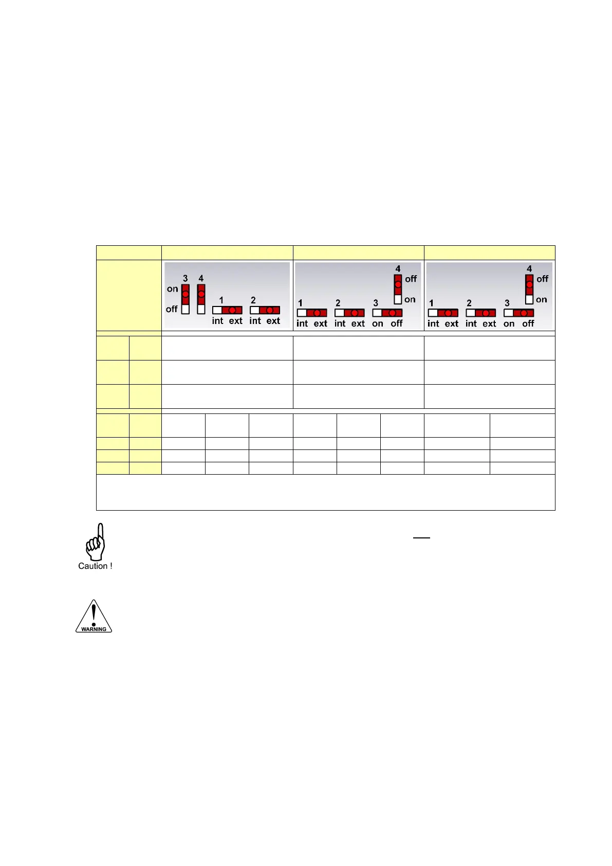
24V. The sensor supply voltage is selected with the switches as indicated in below diagrams.
Sensor supply output
S1: terminal 11. S2: terminal 14
Sensor supply output
S1: terminal 11. S2: terminal 14
Sensor supply output
S1: terminal 11. S2: terminal 14
Limited sensor supply
1.2 / 3V, max 1mA
Limited sensor supply
1.2 / 3V, max 1mA
Limited sensor supply
1.2 / 3V, max 1mA
External sensor supply
as selected by S3 and S4
External sensor supply
as selected by S3 and S4
External sensor supply
as selected by S3 and S4
When only battery power is available (with Type PB), maximum limited sensor supply is 0.1mA.
Isensor,max is the maximum total current taken from terminal 11 and 14.
Vsup,min is the minimum required supply voltage for the selected sensor supply voltage
With Type PD, when external sensor supply voltage is selected and set to Vsupply, the
supply voltage is transferred to the sensor supply output, minus 1V. This means that when a
30V DC supply is connected to terminal 1, the sensor supply output will be around 29V DC.
Setting the sensor supply
Risk of electrocution - High voltage!
Make sure, all the leads to the terminals are disconnected from the F115-P and NEVER
connect mains power to the unit when the protection cover has been removed!
To set the sensor supply, follow these instructions:
1. Open the enclosure as indicated in section 4.3 and carefully remove the cable-connectors.
2. Remove the protective cover by removing the two screws and lifting it upwards. If a battery is
installed inside the cover, disconnect the battery connector from its counterpart.
3. Find and set the switches to the indicated positions, with the aid of a small screwdriver.
4. Reconnect the battery (if applicable) and replace the protective cover using the screws (< 1Nm).
5. Carefully return the cable-connectors and close the enclosure as indicated in section 4.3.