FW_F115-P_M_v2201-01_EN.docx
5.3 TERMINAL CONNECTORS INTRINSICALLY SAFE APPLICATIONS TYPE XI
Take careful notice of all safety and precautionary measures indicated in paragraph
5.2: Electrical installation in hazardous area and review paragraph 5.2.4 and 5.2.5
before applying any field or power supply wiring.
Chapter 4 shows general information regarding the electrical installation of the F115-P. This
chapter gives additional specific information regarding intrinsically safe installation and
overrules the information given in chapter 4.
Normally, the F115-P-XI is classified as group IIB/IIIC. Classification of the unit as group IIC
is possible under certain conditions, as shown in Annex 1 in the previous paragraph.
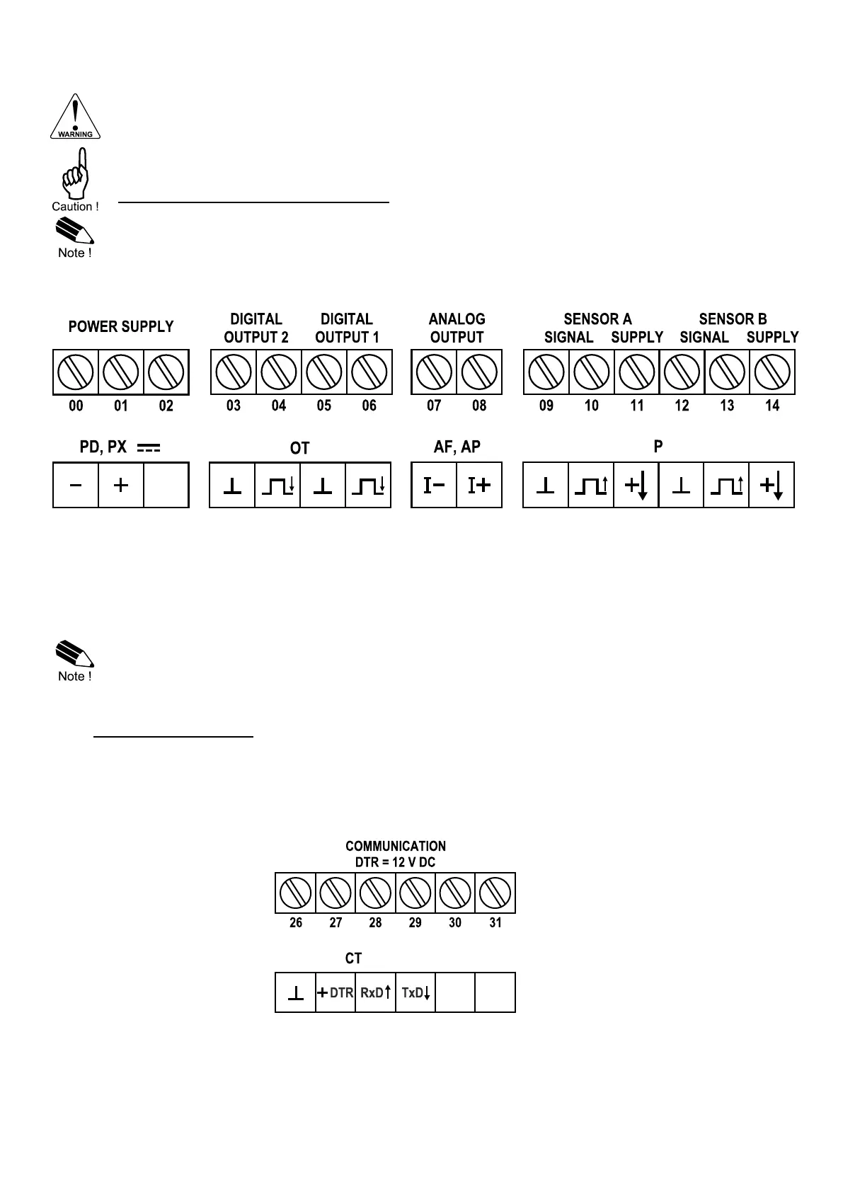
Following terminal connectors are available on the F115-P when supplied with Type XI:
Fig. 33: Overview terminal connectors XI - Intrinsically safe applications
All electrical connections made to the intrinsically safe Type XI terminals must follow the instructions
and safety parameters as given in the product certificate. When installing the F115-P-XI, use the
electrical data and instructions from the model-specific Annex 1 in paragraph 5.2.4 and apply them
to the applicable installation diagrams shown in paragraph 4.6.1 and further.
Only installation diagrams that correspond with the type indications shown in above terminal
connector overview are valid options for intrinsic safety.
For example, only analog outputs Type AP and Type AF are applicable for intrinsic safety.
5.3.1 TERMINAL 26-29: TYPE CT - COMMUNICATION
A TTL communications port for Modbus communication in intrinsically safe applications is available
with this option. See figure below for terminal connections; maximum cable length: 15 meters.
When using the TTL communication option, terminal 27 is used for supplying the interface.
Please connect the DTR (or the RTS) signal of the intrinsically safe interface to this terminal and set
it active (+12V). If no active signal is available it is possible to connect a separate intrinsically safe
supply between terminals 26 and 27 with a voltage between 8V and 24V.
Fig. 34: Terminal connectors Communication (type CT).