FW_F115-P_M_v2201-01_EN.docx
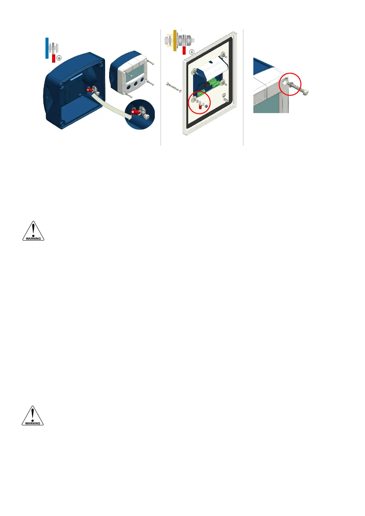
Fig. 12: Protective Earth (PE) connections on metal enclosure
Plastic enclosure
When the F115-P is supplied with a non-metal enclosure (e.g. plastic), the field mount enclosure
meets the requirements of class 2 (double insulated). Therefore any incoming PE conductor can be
terminated with an insulating end cap.
When the F115-P is panel mounted, the installation class and protective earth requirements depend
on the panel or type of cabinet.
4.5.3 FIELD WIRING CONNECTIONS
• Ground an aluminum or stainless steel enclosure properly with a PE wire as indicated to
the Protective Earth terminal. It is the responsibility of the installer to install, connect and
test the Protective Earth connections in accordance with the local and (inter)national
Rules and Regulations.
• When a power supply is connected to the field wiring connections, please also consider
the demands for power supply wiring shown in paragraph 4.5.4.
• The installation must comply with (inter)national requirements and local ordinances.
o Within the Europe Union and the UK, all installations must comply with national
regulations.
o Within Canada all field wiring must conform to Section 18-156 of the Canadian
Electrical Code for installations within Canada.
o Within the United States all field wiring must conform to the National Electric Code,
NFPA 70, Article 501-4(b).
All field wiring enters the F115-P through the bottom of the enclosure and connects to the circuit
assembly inside the enclosure. Wiring is routed through cable glands. Please make sure to order the
F115-P with the correct drilling pattern and thread (metal) or hole (plastic) sizes.
The wire screens (shield) are meant to prevent electromagnetic interference and shall be terminated
at one side to prevent ground loops. Connection of the screen can either be made to the common
ground terminal or at the sensor itself, whichever is appropriate to the application.
Inside of the Fluidwell unit, the various common ground terminals are connected to each other. It is
advised to terminate the wire screens in the vicinity of the sensor and to insulate the wire screen
with a shrink tube at the F115-P side.
4.5.4 POWER SUPPLY WIRING
When not directly supplied from mains (type PM), the external power supply must be an
approved ELV source, insulated from AC mains by double / reinforced insulation per
CSA C22.2 No. 61010-1 / UL / EN / IEC 61010-1.
The F115-P can be powered from an external power supply. An internal power supply is also
available in the form of a lithium battery. When both external and internal power supplies are
available, the internal power supply is interrupted and will act as a backup supply. Note that the
optional backlight only works with an external power supply.