EasyManuals Logo

Fluidwell F115-P User Manual

Fluidwell F115-P
64 pages
To Next Page IconTo Next Page
To Previous Page IconTo Previous Page
Page #54 background imageLoading...
Page #54 background image
FW_F115-P_M_v2201-01_EN.docx
Page 54
APPENDIX C COMMUNICATION VARIABLES
General
The product is fitted with the Modbus communication protocol and can be equipped with various
physical interfaces like RS485 and RS232 (please see device datasheet for available options).
The tables below show the various variables that can be accessed through the communication.
Currently, the function codes supported are:
 (4x references);

The table below shows the Modbus PDU addresses in a decimal format, followed by its hexadecimal
representation (0x0000). When the PLC address range is required (4x references are typically used
by PLCs), please add a value of 40001 to the Modbus PDU address. E.g. reading the serial number
of the product with PLC-based addressing means: 165 + 40001 = register 40166.
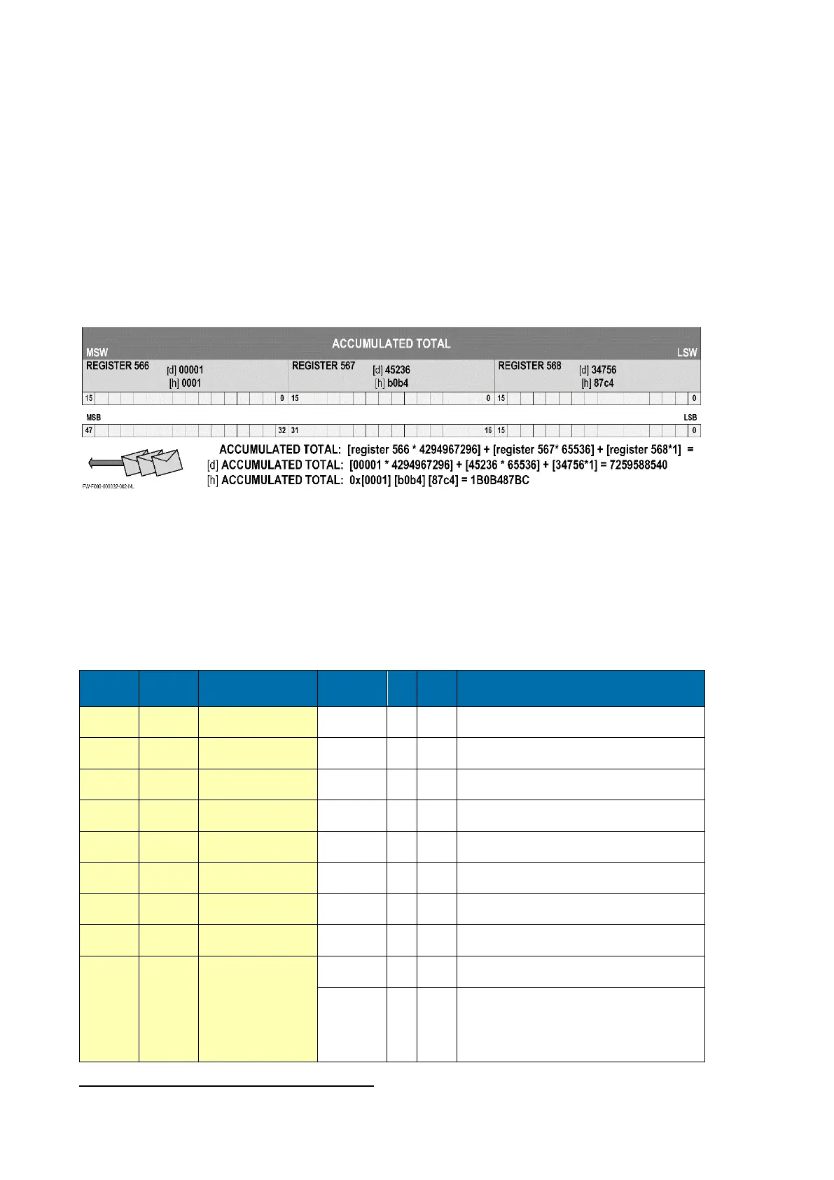
The variables that consist of a multiple register must always read/write in 1 single action!
For this example it is assumed that the variable accumulated total has 3 registers (words) with
address 566, 567 and 568. When a transmission is done, register 566, which acts as the MSW,
arrives first with bit 15 which is the MSB of the lowest addressed word, but is also the MSB (bit 47)
of the complete variable that represents the Accumulated total.
Although most Modbus Masters will support variables that span 2 registers, variables spanning more
registers sometimes require you to manually calculate the resulting value.
For additional information regarding using your Modbus device, please read our General Modbus

or your distributor.
Runtime variables
PDU
ADDRESS
REGISTER
VARIABLE
RUN TIME
NO.
REGISTERS
R/W
TYPE
VALUE / REMARKS
[d] 572
[h] 0x23C
40573
Flow rate A
2
R
uint32
0…9999999, Representation: unit, time
[d] 566
[h] 0x236
40567
Total A
3
R*
uint48
0…9999999999, Representation: unit
[d] 560
[h] 0x230
40561
Accumulated Total A
3
R
uint48
0…99999999999999, Representation: unit
[d] 588
[h] 0x24C
40589
Flow rate B
2
R
uint32
0…9999999, Representation: unit, time
[d] 1078
[h] 0x436
41079
Total B
3
R*
uint48
0…99999999999999, Representation: unit
[d] 1072
[h] 0x430
41073
Accumulated Total B
3
R
uint48
0…99999999999999, Representation: unit
[d] 1596
[h] 0x63C
41597
Differential Flow rate
2
R
uint32
0…9999999, Representation: unit, time
[d] 1590
[h] 0x636
41591
Differential Total
3
R*
uint48
0…99999999999999, Representation: unit
[d] 1584
[h] 0x630
41585
Differential
Accumulated Total
3
R
uint48
0…99999999999999, Representation: unit
[d] 516
[h] 0x204
40517
error status (bitfield)
1
R
uint16
[d] 0 = no error
[d] 1 = display error
[d] 2 = data-storage error
[d] 3 = error 1 + error 2 simultaneously
[d] 4 =: initialization error
Reading flow rate, total or accumulated total: The returned values are given including the
decimals and represent the actual value. The given value may differ from the value that is shown on

Table of Contents

Other manuals for Fluidwell F115-P

Questions and Answers:

Question and Answer IconNeed help?

Do you have a question about the Fluidwell F115-P and is the answer not in the manual?

Fluidwell F115-P Specifications

General IconGeneral
BrandFluidwell
ModelF115-P
CategoryMeasuring Instruments
LanguageEnglish

Related product manuals