4.6.2 TERMINAL 03-04: NEGATIVE FLOW OUTPUT R2
This output is switched when total is counting down. Functionality is set with Setup menu 9. For
options and wiring schemes see below, terminals 05-06.
4.6.3 TERMINAL 05-06: PULSE OUTPUT R1
This output is activated when a certain totalized flow has passed (set in Setup menu 9).
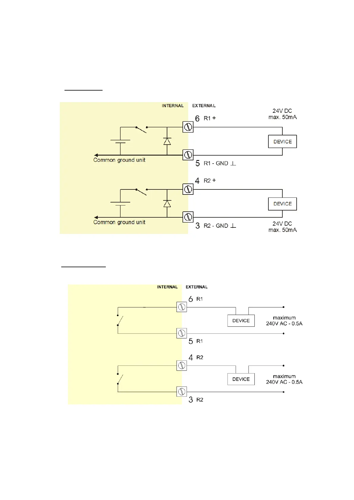
Type OA
An active 24V DC output is available with this option.
Max. driving capacity 50mA@24V per output. (Requires power supply type PD/PF/PM).
Fig. 14: Terminal connections - Active output (typical)
Type OR
A mechanical relay output is available with this option.
Max. switch power 240V 0,5A per output. (Requires power supply type PD/PF/PM). Be sure that the
output frequency does not exceed 5Hz, else the relay life time will be reduced significantly.
Fig. 15: Terminal connections - Mechanical relay output (typical)