FW_F115-P_M_v2201-01_EN.docx
Use the control panel to navigate through SETUP-level
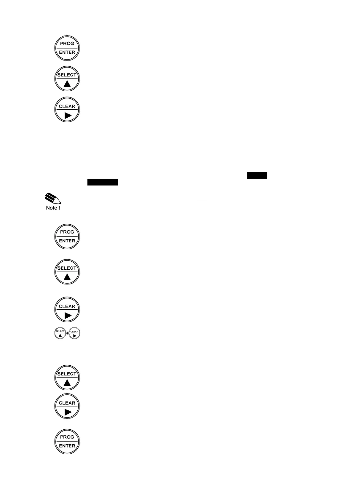
PROG-key
When a function is selected, this key is used to start the programming sequence.
When only a function group is selected (and no function), this key is used to scroll back
a function group (e.g. 3 → 2 → 1 → 3).
SELECT-key
This key is used to select the next function in the list (e.g. 1 → 1.1 → 1.2 → 1). When
the top of the list is reached, it will wrap around and return to the function group
selection.
CLEAR-key
This key is used to select the previous function in the list (e.g. 1.2 → 1.1 → 1 → 2).
When the bottom of the list is reached, it will return to the function group selection.
When only a function group is selected (and no function), this key is used to scroll to
the next function group. (e.g. 1 → 2 → 3 → 1).
3.2.3 PROGRAMMING SEQUENCE
After selecting a function at SETUP-level, a new value can be programmed using the control panel.
A function either contains a value (a number with optionally a decimal point, e.g. 123.45) or a list
with items (e.g. Disable Enable).
For each function that needs to change, navigate to that function and follow the steps indicated
below. During the programming sequence, the display will deactivate the SETUP indicator and
activate the PROGRAM indicator.
When programming new values, alterations will only be set after the PROG-key has been
pressed to confirm the new value! (STEP 3)
Step 1: Starting the programming sequence
PROG-key
When a function is selected at SETUP-level, this key is used to start the programming
sequence.
Step 2a: Changing a value
SELECT-key
This key is used to increment the selected digit.
When the entered value is out of range, the increase sign or decrease-sign will
be displayed while you are programming. If this value is confirmed by pressing the
PROG-key, the value will be brought within a valid range automatically.
CLEAR-key
This key is used to select the next digit. If a decimal point can be set, this will be
included in the sequence as well (e.g. [decimal point] → digit 1 → digit 2→ digit 3 →
[decimal point].
SELECT-key + CLEAR-key
The combination of the SELECT-key and CLEAR-key is used to select a negative
value. When a value can also be entered as a negative number, pressing the SELECT-
key and CLEAR-
Step 2b: Changing the selected item in a list
SELECT-key
This key is used to select the next item in the list (e.g. Disable → Enable).
At the end of the list, the selection will wrap around to the first selection.
CLEAR-key
This key is used to select the previous item in the list (e.g. Enable → Disable ).
At the bottom of the list, the selection will wrap around to the last selection.
Step 3: Finishing the programming sequence
PROG-key
During the programming sequence, this key is used to confirm the new value and
return to SETUP-level. To cancel the operation, either press the PROG-key for 3
seconds or wait for 20 seconds: the programming sequence is cancelled and the
former value is reinstated.