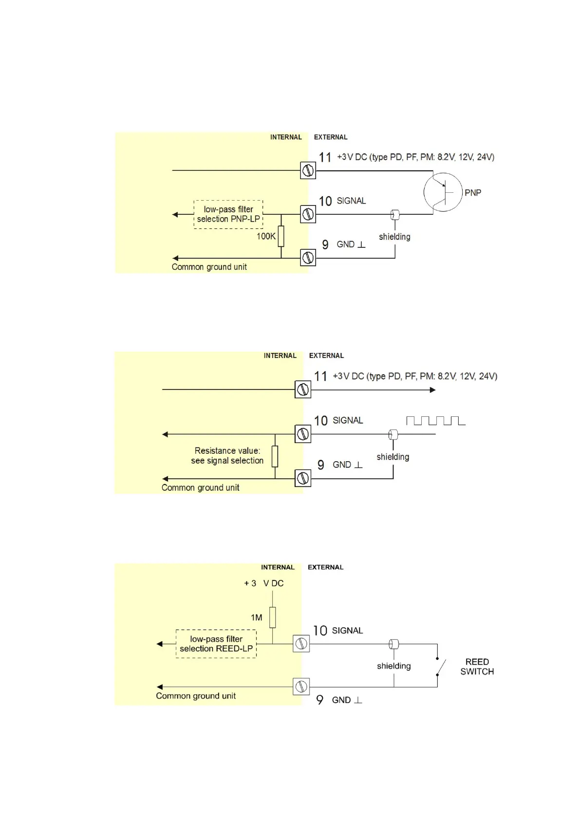
Pulse-signal PNP / PNP-LP
The F115-P is suitable for use with flowmeters which have a PNP output signal. 3V is offered on
terminal 11 which has to be switched by the sensor to terminal 10 (SIGNAL). For a reliable pulse
detection, the pulse amplitude has to go above 1.2V. Signal setting PNP-LP employs a low-pass
signal noise filter, which limits the maximum input frequency (read chapter 3).
A sensor supply voltage of 8.2, 12 or 24V DC can be provided with power supply type PD, PF, PM.
For a signal detection level of 50% of the supply voltage: please refer to "active signals".
Fig. 25: Terminal connections - PNP signal input (typical)
Active signal 8.2V, 12V and 24V
If a sensor gives an active signal (read chapter 3).The detection levels are 50% of the selected
supply voltage; approx. 4V (8.1 DC) or 6V (12 DC) or 12V (24 DC). Active signal selection may well
be desired in case of power supply type PD, PF, PM is available for sensor supply.
Fig. 26: Terminal connections - Active signal input (typical)
Reed-switch
The F115-P is suitable for use with flowmeters which have a reed-switch. To avoid pulse bounce
from the reed-switch, it is advised to select REED LP low-pass filter (read chapter 3).
Fig. 27: Terminal connections - Reed-switch signal input (typical)