Industrial ScopeMeter®
Fieldbus Mode
47
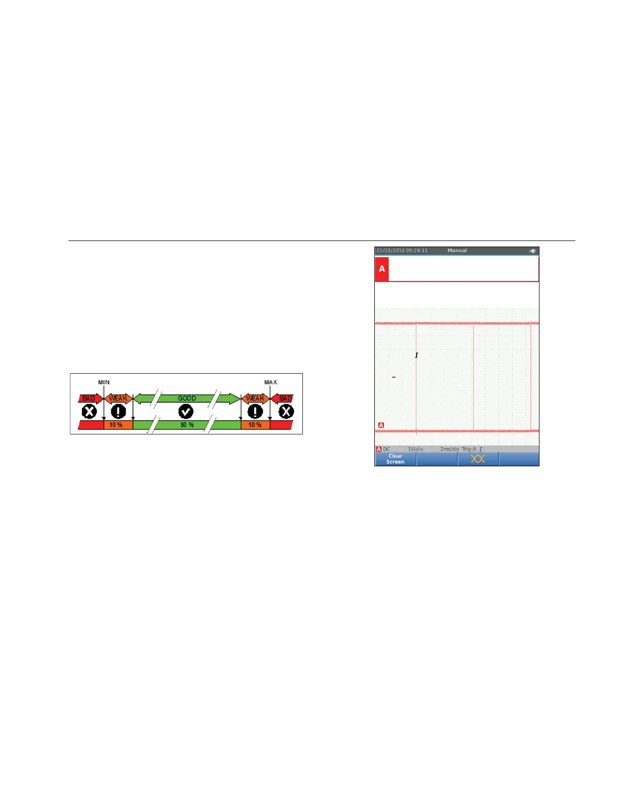
Figure 12 shows the bus health indicator boundaries. The
high level voltage of a bus must be between +3.0 V (MIN)
and +15.0 V (MAX). Depending on the measurement
result, the displayed indicator will be:
f
Result is between 4.2 and 13.8V. (10 % of
12 V = 1.2 V)
d
Result is between 3 V and 4.2 V, or between
13.8 V and 15 V.
e
Result is <3 V or >15 V.
hxv34.eps
Figure 12. Bus Health Indicator Boundaries
How to View the Bus Waveform Screen
To view the waveform eye pattern of the bus voltage:
1. Push 3. The screen shows the eye pattern. The
screen shows the waveforms of one bit time
triggered on a positive, as well as, on a negative
edge in persistence mode.
2. Push 1 to clear the persisted waveforms and
restart to show the waveform.
hxv35.eps
3. Push to freeze the screen. Push again to
clear the persistence waveform and restart the
waveform eye pattern.
1.888.610.7664 sales@GlobalTestSupply.com
Fluke-Direct.com
 Loading...