732B/734A
Instruction Manual
3-10
734A DC REFERENCE STANDARD
732B DC STANDARD
AC PWR IN CAL CHARGE LOW BAT
10V 1.018V CHASSIS
GUARD1.018V COM10V COM
SERIAL NUMBER
732B DC STANDARD
AC PWR IN CAL CHARGE LOW BAT
10V 1.018V CHASSIS
GUARD1.018V COM10V COM
SERIAL NUMBER
732B DC STANDARD
AC PWR IN CAL CHARGE LOW BAT
10V 1.018V CHASSIS
GUARD1.018V COM10V COM
SERIAL NUMBER
1
5 4
3
2
k9f.eps
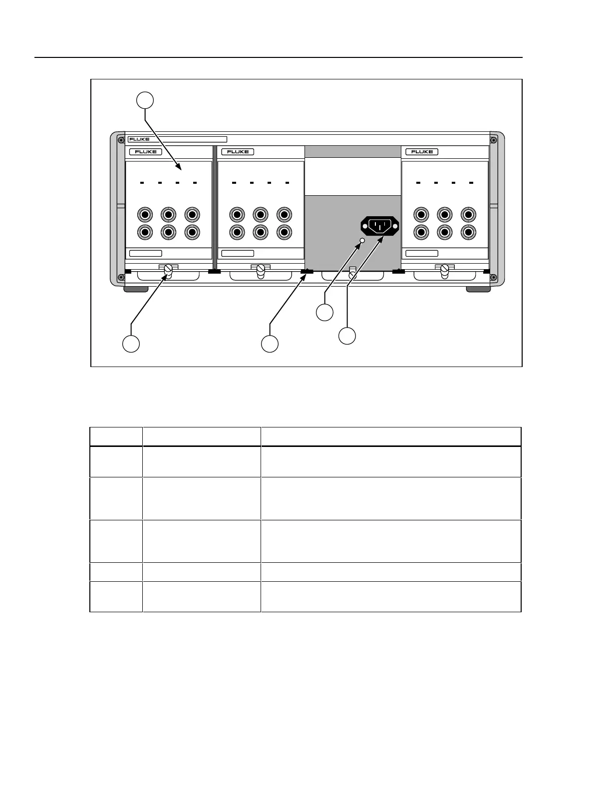
Figure 3-5. 734A-7001 Instrument Enclosure Front Panel Features
Table 3-5. 734A-7001 Instrument Enclosure Front Panel Features
Item Feature Description
1 Instrument Bay There are four instrument bays in the 734A-7001 Instrument
Enclosure. Each holds one Model 732B or 732B-7001 unit.
2 AC Power Bus Connector This internal connector automatically mates with the 732B or
732B-7001 rear panel ac power input when you install a 732B
unit into the enclosure.
3 Alignment Pin This alignment pin mates with an alignment hole on the rear
panel of the 732B or 732B-7001. It ensures that the ac line
connectors are aligned.
4 Guide Guides separate each instrument bay.
5 Locking Lever Tighten the screw to lock a 732B or 732B-7001 in place inside
the instrument enclosure.
www.valuetronics.com