732B/734A
Instruction Manual
3-14
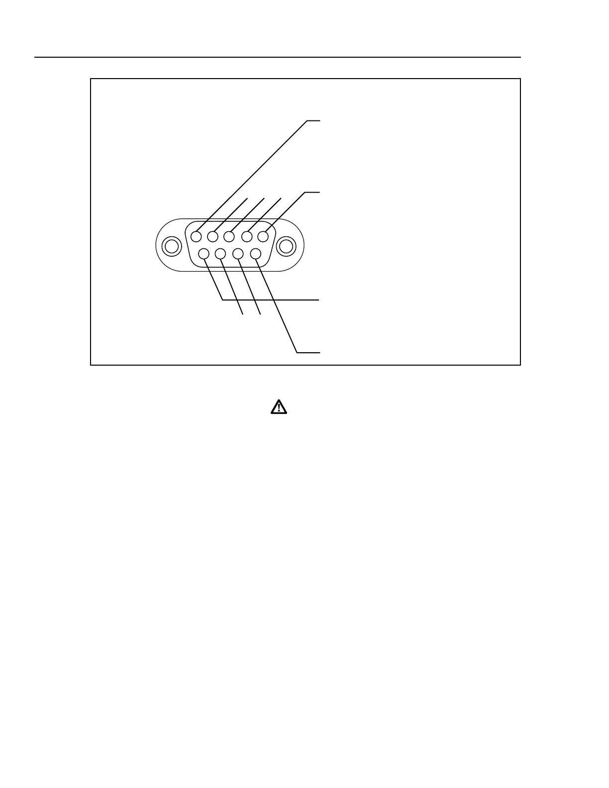
12 3 4 5
9
876
DESCRIPTION
EXT BAT COMMON
BAT +
EXT BAT COMMON
BAT +
PIN
NUMBER
1
5
6
9
NOT USED
NOT USED
k12f.eps
Figure 3-8. 732B-7001 BAT OUT Connector Pinout
Warning
To avoid explosion or fire, be careful not to short the battery
terminals during battery replacement. Only qualified personnel
should replace the battery.
Connecting Cables to the Output 3-14.
Caution
To avoid cracking or jamming the plastic binding post
insulators, tighten them only with finger pressure. Do not use
tools.
Shielded test leads should be used for connecting anything to the standard output binding
posts. You can use banana plugs, spade lugs, or bare wire to attach cables to the binding
posts. The best choice is shielded cables with low-thermal emf connectors such as Fluke
Model 5440-7002 Low Thermal Cables. See "Thermal EMFs" further on in this section
for more information. Figure 3-9 shows the cable connections for applying the 10V
source required by the 5700A during its calibration procedure.
www.valuetronics.com