732B/734A
Instruction Manual
5-4
You have a choice of two 10V output calibration procedures. Both procedures use direct
comparison between your 732B, called the Unit Under Test (UUT), and a certified 732B
or 732A to calibrate the 10V output. In the first procedure, you do not adjust the 732B
under test. In the second procedure, you adjust the 10V output of the 732B under test so
that it is equal to the reference standard. The 1.018V output is divided down from the
10V output, and is not independently adjustable.
Note
Equivalent equipment and methods may be substituted for the following
calibration procedures as long as the equipment and standards used are at
least as accurate as those specified.
Preparing for Calibration 5-6.
Choose either the procedure with adjustment or without adjustment. Table 5-1 lists the
equipment you will need to calibrate the 732B. Before you proceed, leave the 732B
powered on with the BAT switch set to l and the standard plugged into ac line power for
24 hours. This stabilizes the oven temperature and fully charges the internal battery. If
you want to calibrate the 732B without adjusting it, skip to "10V Calibration Without
Adjustment."
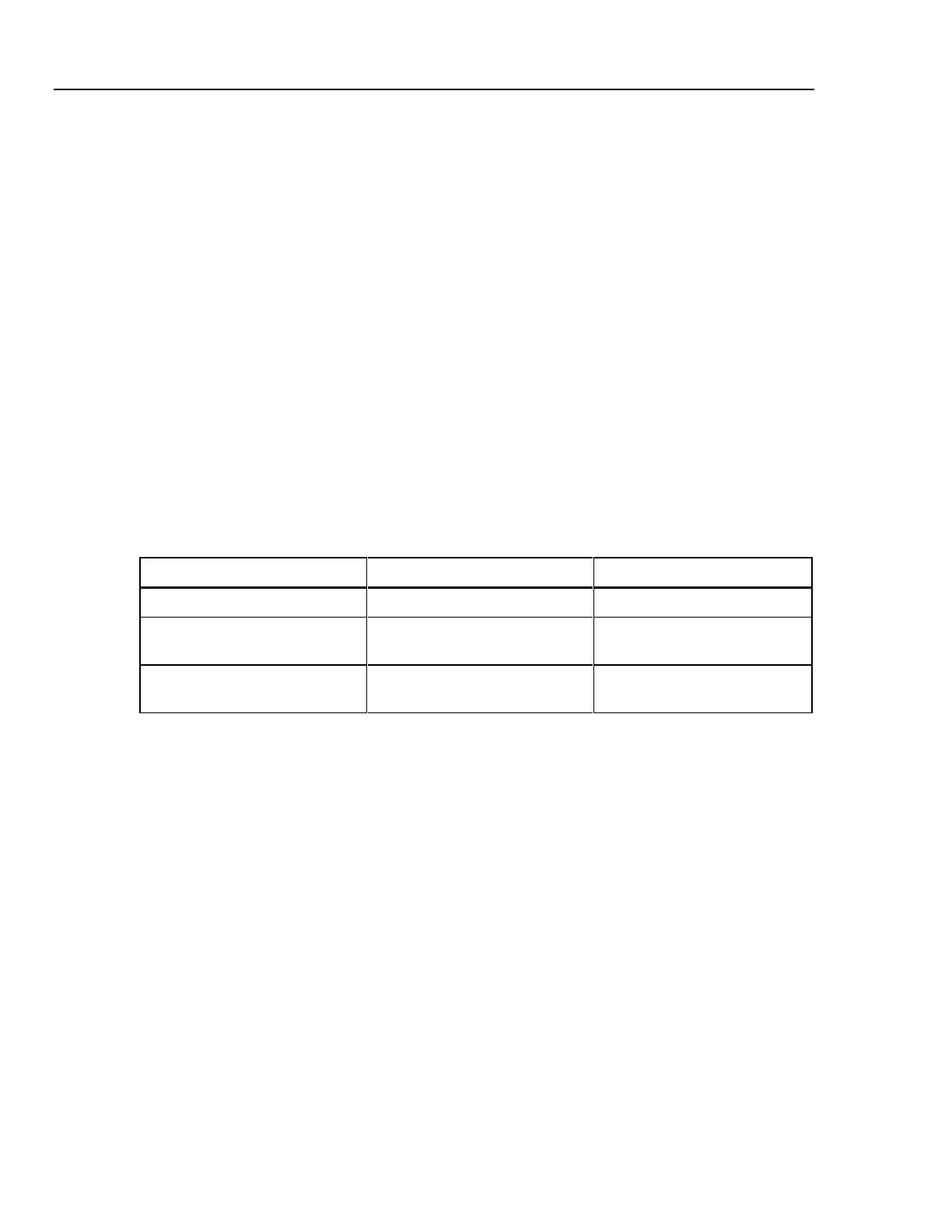
Table 5-1. Equipment Required for Calibration
Equipment Manufacturer Minimum Use Specifications
Null Detector Fluke 845AB or 845AR 0.1 µV Resolution
Low Thermal Shielded Test
Leads
Any NA
Calibrated 10V Reference
Standard
Fluke 732B Certified to the uncertainty
required for your laboratory
Preparing for 10V Calibration with Adjustment 5-7.
In this method, you to adjust the 10V output of the 732B during the calibration
procedure. To access the bcd adjustment switches, perform the "Initial Access
Procedure" in this section. The bcd output adjustment switches are located on top near
the front of the instrument as shown in Figure 5-2. Each switch has the numbers 0
through 9 marked on it. Each higher numbered switch setting causes the output voltage
to increment a positive amount.
The switches are labeled to represent the approximate 10V output shift in ppm as
follows:
• Switch "100" (ppm) adjusts the output in increments of approximately 1 mV to 1.5
mV. The usable range of this switch is 0 to 3. Positions greater than 3 are not
implemented and will simply repeat positions 0 through 3.
• Switch "10" (ppm) adjust the output in increments of approximately 100 µV to 150
µV. The usable range of this switch is 0 to 9.
• Switch "1.0" (ppm) adjusts the output in increments of approximately 10 to 15 µV.
The usable range of this switch is 0 to 9.
• Switch "0.1" (ppm) adjusts the output in increments of approximately 1 µV. The
usable range of this switch is 0 to 9.
www.valuetronics.com