Operation
Connecting Cables to the Output
3
3-15
732B DC STANDARD
AC PWR IN CAL CHARGE LOW BAT
10V 1.018V CHASSIS
GUARD1.018V COM10V COM
SERIAL NUMBER
5700A
HI
HI
LO
LO
HI
OUTPUT
V A
SENSE
V
AUX
CURRENT
GUARD
GROUND
WIDEBAND
ΩΩ
732B
NOTE:
GUARD IS CONNECTED TO
GROUND AT ONLY ONE
PLACE.
k13f.eps
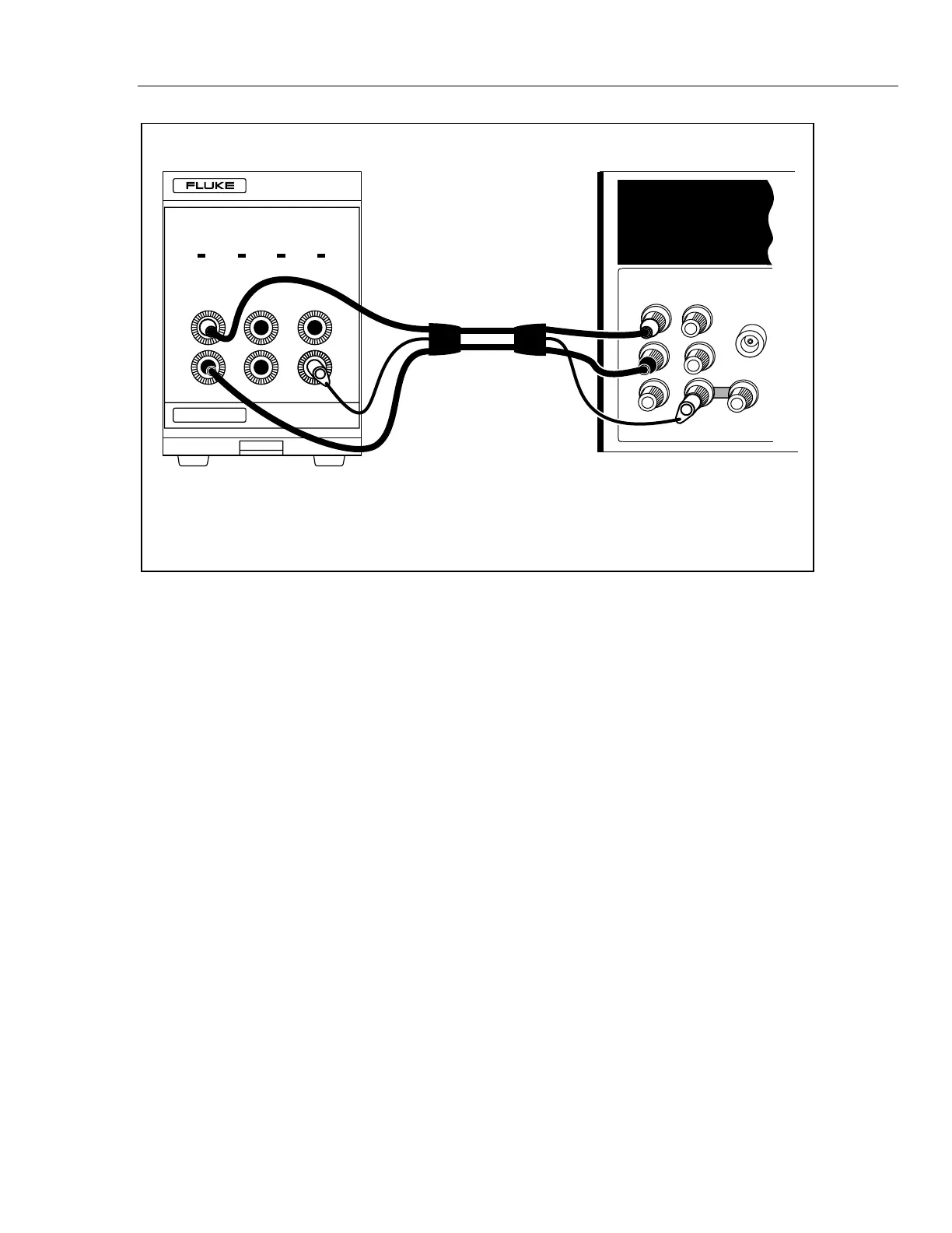
Figure 3-9. Typical 732B Cable Connections
Connecting the GUARD and GROUND 3-15.
Note
Spurious currents in the COM (common) wires will degrade measurements
at the accuracy level of the 732B. Make sure the GUARD terminals of all
interconnected instruments are tied to earth ground at one point and one
point only in the system, and all LO or COM terminals are tied to GUARD
at only one point in the system.
Use the GUARD connection when any of the following conditions exists:
1. When a potential exists between equipment and a power line ground.
2. When you use long connection leads to connect a high-impedance load.
3. When you are operating the standard in a high EMI environment.
4. To avoid the effects of electrostatic charge buildup on people.
The GUARD is an electrical shield around the sensitive analog circuitry, insulated from
chassis ground and the rest of the standard. The GUARD provides a low-impedance path
for common-mode noise and ground currents. The guard eliminates the chance of ground
currents in the signal leads caused by plugging the line cord into an ac outlet at a
different ground potential than the chassis ground of the interconnected instruments.
Ground currents can occur if instrument guards are not connected properly, resulting in
annoying and often subtle measurement errors. The basic rule is, in any system of
measurement instruments, the guards within all instruments should be grounded at one
and one point only. Circuit common (the 10V COM or 1.018V COM) should be
electrically connected to the other instrument guards at one and only one point as well,
www.valuetronics.com