OPERATION
FRONT PANEL FEATURES
3.
Refer to Figure 2-1, item 5 for the location
of
the fuse holder. The fuse holder
is
an
integral
part
of
the mA input connector.
4.
Using a coin or wide blade screwdriver, push in
while turning the fuse holder in the direction
of
the arrow on the front panel decal.
5.
Pull
out
the fuse holder
and
replace the
defective fuse.
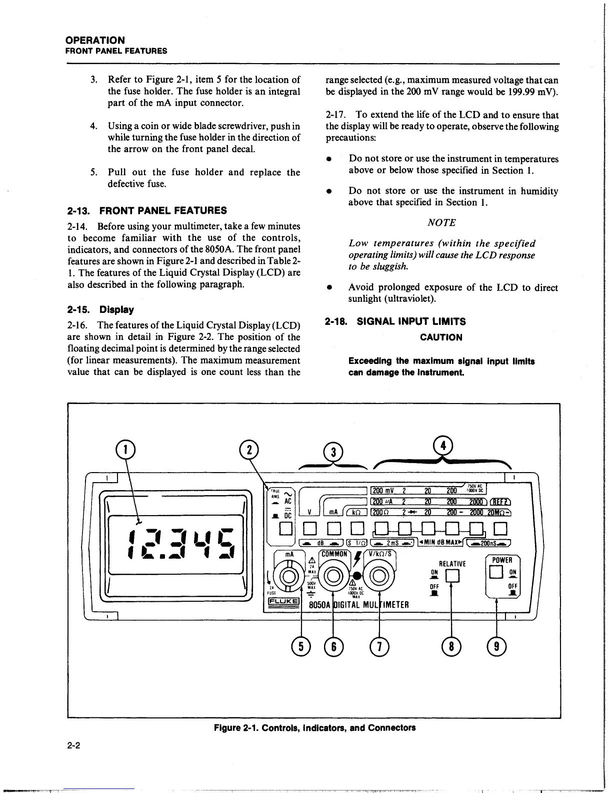
2-13. FRONT PANEL FEATURES
2-14.
Before using your multimeter, take a
few
minutes
to become familiar with the use
of
the controls,
indicators, and connectors
of
the 8050A. The front panel
features are shown in Figure
2-1
and described in Table
2-
1.
The features
of
the Liquid Crystal Display (LCD) are
also described in the following paragraph.
2-15.
Display
2-16. The features
of
the Liquid Crystal Display (LCD)
are shown in detail in Figure
2-2.
The position
of
the
floating decimal point
is
determined by the range selected
(for linear measurements). The maximum measurement
value that can be displayed
is
one count
less
than the
range selected (e.g., maximum measured voltage that can
be displayed in the
200
mV
range would be 199.99 mV).
2-17.
To extend the life
of
the LCD and to ensure that
the display will
be
ready to operate, observe the following
precautions:
• Do
not
store
or
use the instrument in temperatures
above
or
below those specified in Section
1.
• Do not store
or
use the instrument in humidity
above that specified in Section
1.
NOTE
Low
temperatures
(within
the
specified
operating limits) will cause the
LCD
response
to be sluggish.
• Avoid prolonged exposure
of
the LCD to direct
sunlight (ultraviolet).
2-18. SIGNAL INPUT LIMITS
CAUTION
Exceeding the maximum signal Input limits
can damage the Instrument.
,_(L
r""'
__
...,0~4---....,
I
2-2
•:•:•t.•C
f L .... f f
....
I
\
Figure 2-1. Controls, Indicators, and Connectors
ON
.....
OFF
..
RELATIVE
POWER
D
.2!
OFF
....
8 9
------·
--~·--