THEORY OF OPERATION
TRUE-RMS CONVERTER
3-28.
As
Part
C
of
Figure
3-5
shows, when the 2 mS,
20on, or 2
kn
range
is
selected, the voltage drop across
the unknown resistance
is
measured in relation to the
voltage drop across the known· reference resistor, and
since the same current
is
flowing through both resistors,
the value
of
the unknown resistance can
be
computed
using the formula:
VRx
Rx
-V
!lREF
=
RREF
(Minus V
OREF
is
necessary for de-integration during the
Read period.)
3-29.
As
Part
C
of
Figure
3-5
shows, when any range but
2 mS, 20on,
or
2
kn
is
selected, the voltage drop across
the unknown resistance
is
measured, and
C7
charges up to
the ohms voltage source, VH. During the Read period,
the
a/
d buffer subtracts the voltage on
C7
from VL,
thereby obtaining
-V
nREF.
3-30.
For
conductance
measurements,
the
microcomputer inverts the
kn
measurements
(S=
l /
n)
by
reversing the order
of
the Integrate and Read periods
of
the
a/
d converter.
3-31. True-RMS Converter
3-32.
The true-rms converter
is
made up of two ac
buffers and a hybrid true-rms converter.
3-33.
AC
BUFFERS
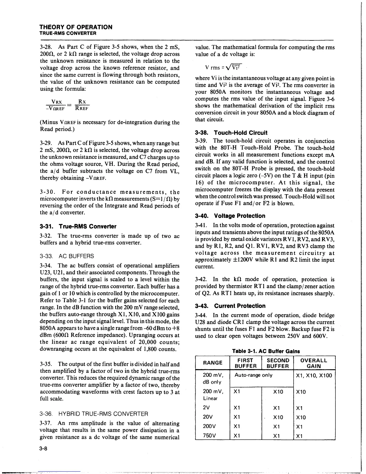
3-34. The ac buffers consist
of
operational amplifiers
U23,
U2l, and their associated components. Through the
buffers, the input signal
is
scaled to a level within the
range of the hybrid true-rms converter. Each buffer has a
gain
of
l
or
l 0 which is controlled by the microcomputer.
Refer to Table 3-l for the buffer gains selected for each
range. In the
dB
function with the
200
m V range selected,
the buffers auto-range through XI,
XIO,
and
XlOO
gains
depending
on
the input signal level. Thus in this mode, the
8050A appears to have a single range from
--60
dBm to
+8
dBm (600n Reference impedance). Upranging occurs
at
the
linear
ac
range
equivalent
of
20,000
counts;
downranging occurs
at
the equivalent
of
l ,800 counts.
3-35.
The output
of
the first buffer
is
divided in half and
then amplified
by
a factor of two in the hybrid true-rms
converter. This reduces the required dynamic range
of
the
true-rms converter amplifier by a factor
of
two, thereby
accommodating waveforms with crest factors up to 3
at
full scale.
3-36. HYBRID TRUE-RMS CONVERTER
3-37.
An rms amplitude
is
the value
of
alternating
voltage that results in the same power dissipation in a
given resistance as a de voltage
of
the same numerical
3-8
_
...
...,....,~
'"'
0
T·--1-·1-
value. The mathematical formula for computing the rms
value
of
a de voltage
is:
Vrms=VW
where
Vi
is the instantaneous voltage
at
any given point in
time and
Vi
2
is
the average
of
Vi
2
•
Therms
converter in
your 8050A monitors the instantaneous voltage and
computes the rms value
of
the input signal. Figure
3-6
shows the mathematical derivation
of
the implicit rms
conversion circuit in your 8050A and a block diagram
of
that circuit.
3-38. Touch-Hold Circuit
3-39.
The touch-hold circuit operates in conjunction
with the 80T-H Touch-Hold Probe. The touch-hold
circuit works in all measurement functions except mA
and
dB.
If
any valid function
is
selected, and the control
switch on the 80T-H Probe
is
pressed, the touch-hold
circuit places a logic zero (-5V) on the T
& H input (pin
16)
of
the
microcomputer.
At
this
signal,
the
microcomputer freezes the display with the data present
when the control switch was pressed. Touch-Hold will not
operate if Fuse
Fl
and/
or
F2
is
blown.
3-40. Voltage Protection
3-41.
In the volts mode
of
operation, protection against
inputs and transients above the input ratings
of
the 8050A
is
provided
by
metal oxide varistors RV l, R
V2,
and R
V3,
and by
RI,
R2,
and
QI.
RVI, RV2, and
RV3
clamp the
voltage
across
the
measurement
circuitry
at
approximately ±1200V while
RI
and
R2 limit the input
current.
3-42.
In
the
kn
mode
of
operation, protection
is
provided by thermistor RT l and the clamp/ zener action
of
Q2.
As
RTI heats up, its resistance increases sharply.
3-43. Current Protection
3-44.
In the current mode
of
operation, diode bridge
U28
and diode
CRI
clamp the voltage across the current
shunts until the fuses
Fl
and F2 blow. Backup fuse F2
is
used to clear open voltages between
250V
and
600V.
Table 3-1.
AC
Buffer Gains
RANGE
FIRST
SECOND
OVERALL
BUFFER
BUFFER
GAIN
200 mV, Auto-range
only
X1, X10, X100
dB
only
200 mV,
X1
X10 X10
Linear
2V
X1
X1
X1
20V
X1
X10
X10
200V
X1
X1
X1
750V
X1
X1
X1