MAINTENANCE
CALIBRATION ADJUSTMENTS
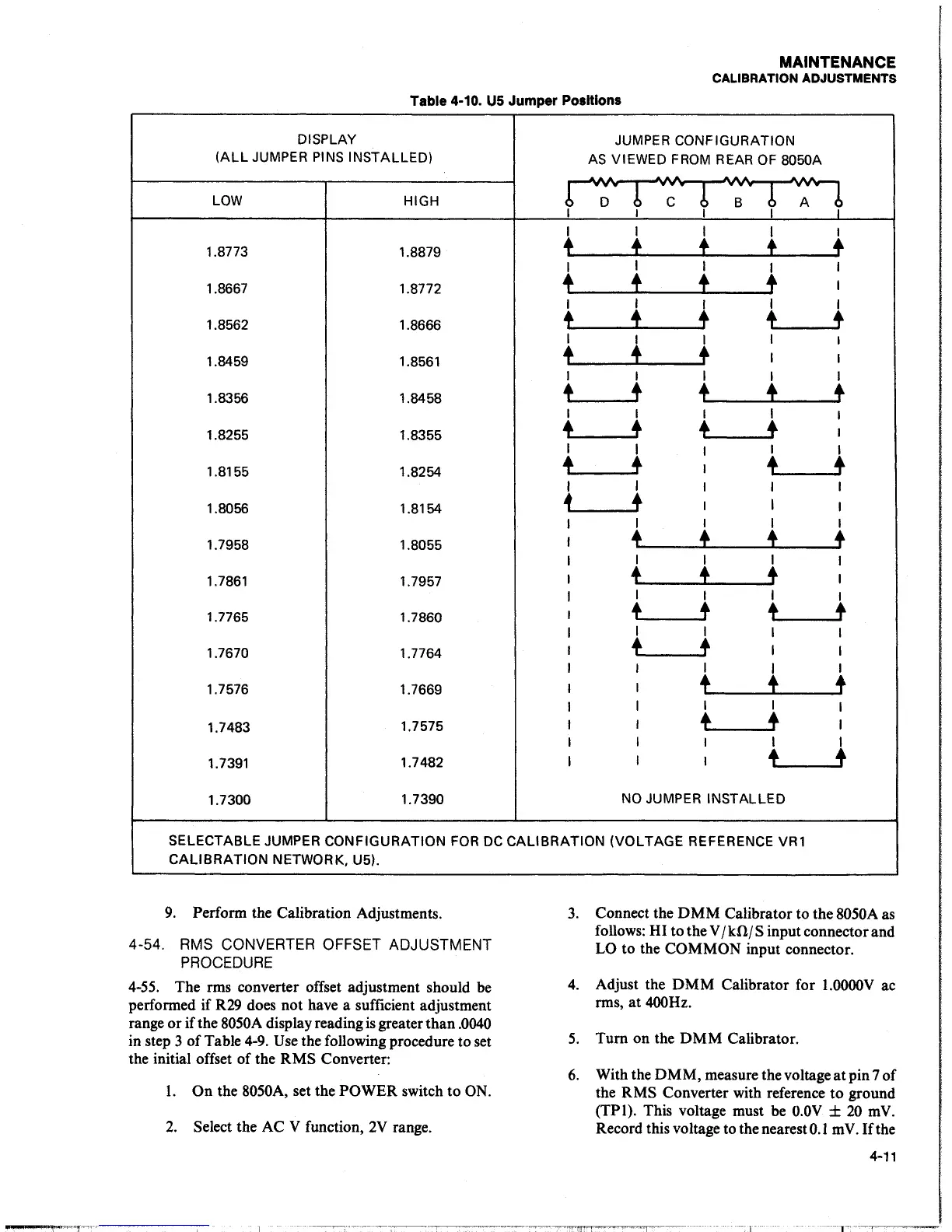
Table 4-10.
US
Jumper Positions
DISPLAY
JUMPER CONFIGURATION
(ALL
JUMPER
PINS
INSTALLED)
AS
VIEWED
FROM
REAR
OF
8050A
.
...
...
&&
&
....
&&
~
. . .
~
...
+
..
+
..
...
~
LOW
HIGH
D
c
B
A
I
I
I
I
I
1.8773
1.8879
t
~
t t
+
I
I
I
I
I
1.8667
1.8772
+
t
t
t
I
I
I
I
I
I
1.8562
1.8666
t
f
t
~
t
I
I
I
I
I
1.8459 1.8561
t
f
t
I
I
I
I I
I I
1.8356
1.8458
t
t
~
f
t
I I
I
I
I
1.8255 1.8355
+
t
t
t
I
I
I
I
I
I
1.8155
1.8254
t
t
I
t
t
I
I
I I
I
1.8056 1.8154
~
t
I
I
I
I
I
I
I
1.7958
1.8055
~
f
i
+
I
I I
I
1.7861 1.7957
t
f
t
I
I
I I
I
1.7765
1.7860
t
t
t
t
I
I
I I
1.7670 1.7764
t
t
I
I
I I
I
I
1.7576
1.7669
I
t t
+
I
I
I
I
1.7483
1.7575
I
I
t t
I
I
I
I I
I
1.7391
1.7482
I
I
I
+
t
1.7300
1.7390
NO
JUMPER INSTALLED
SELECTABLE JUMPER CONFIGURATION
FOR
DC
CALIBRATION (VOLTAGE REFERENCE
VRl
CALIBRATION
NETWORK, U5).
9.
Perform the Calibration Adjustments.
4-54.
RMS CONVERTER OFFSET ADJUSTMENT
PROCEDURE
4-55.
The rms converter offset adjustment should
be
performed if
R29
does not have a sufficient adjustment
range or if the 8050A display reading
is
greater than
.0040
in step 3 of Table
4-9.
Use
the following procedure to set
the initial offset of the RMS Converter:
I.
On the 8050A, set the POWER switch to ON.
2.
Select the AC V function,
2V
range.
3.
Connect the
DMM
Calibrator to the 8050A
as
follows: HI to the V /kO./S input connector and
LO to the COMMON input connector.
4.
Adjust the
DMM
Calibrator for
l.OOOOV
ac
rms,
at
400Hz.
5.
Turn on the
DMM
Calibrator.
6.
With the
DMM,
measure the voltage
at
pin 7 of
the RMS Converter with reference
to
ground
(TPl). This voltage must be
O.OV
±
20
mV.
Record this voltage to the nearest
0.1
m
V.
If
the
4-11
--1