MAINTENANCE
ACCESS PROCEDURES
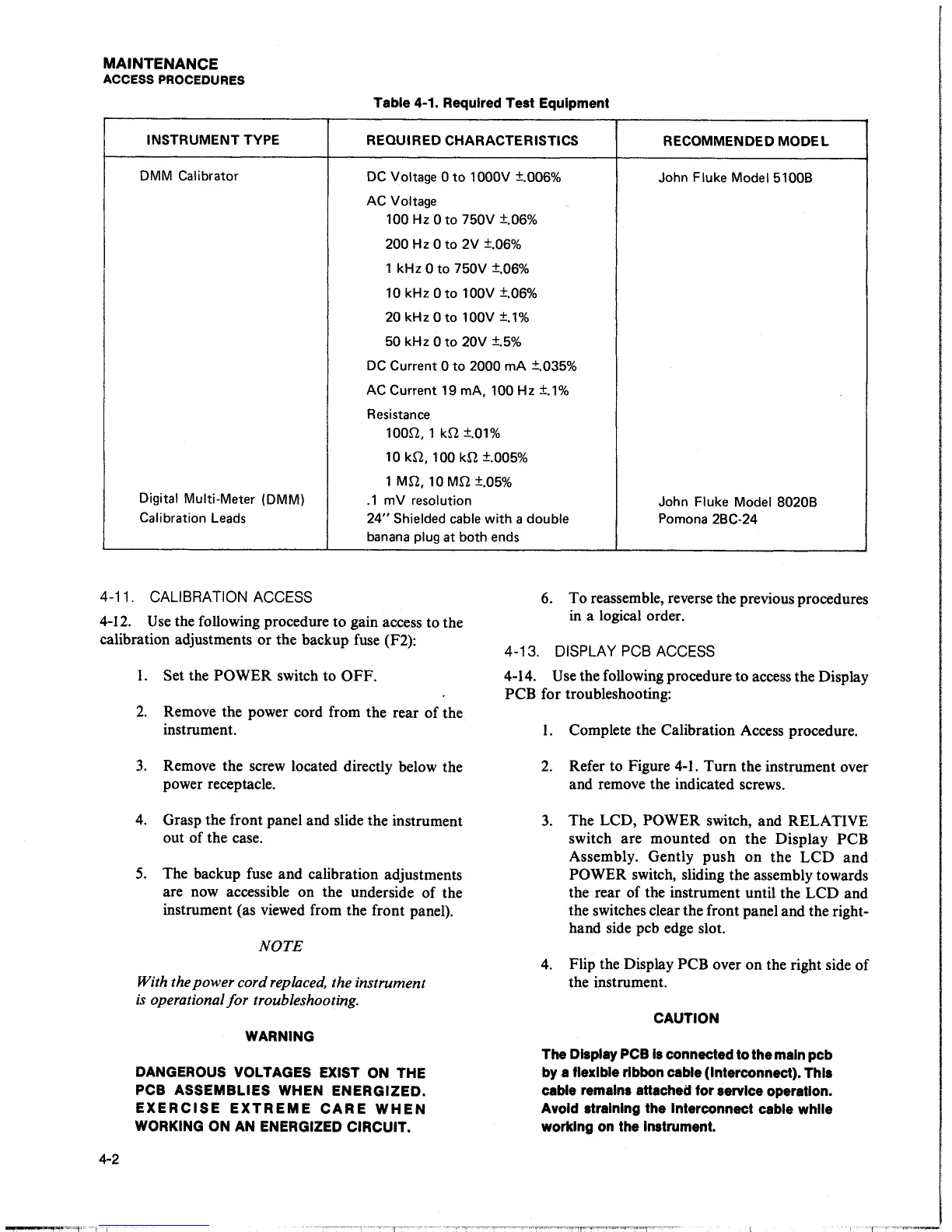
Table
4-1. Required Test Equipment
INSTRUMENT
TYPE
REQUIRED CHARACTERISTICS
RECOMMENDED
MODEL
DMM
Calibrator
DC
Voltage
Oto
1000V ±.006%
John
Fluke Model 51008
AC Voltage
100
Hz
0
to
750V ±.06%
200
Hz
0
to
2V ±.06%
1 kHz
0
to
750V ±.06%
10
kHz 0
to
100V ±.06%
20
kHz 0
to
100V
±.1%
50
kHz 0
to
20V
±.5%
DC
Current
0
to
2000
mA
±.035%
AC
Current 19
mA, 100
Hz
±.1%
Resistance
100Q,
1
kQ
±.01%
10
kQ,
100
kQ
±.005%
1
MQ,
10
MQ
±.05%
Digital Multi-Meter (DMM)
.1
mV
resolution
John
Fluke Model 8020B
Calibration
Leads
24"
Shielded cable
with
a
double Pomona
2BC-24
banana
plug
at both
ends
4-11. CALIBRATION
ACCESS
6. To reassemble, reverse the previous procedures
in a logical order.
4-12.
Use
the following procedure to gain access to the
calibration adjustments or the backup
fuse
(F2):
4-2
I.
Set
the POWER switch to OFF.
2.
Remove the power cord from the rear of the
instrument.
3.
Remove the screw located directly below the
power receptacle.
4.
Grasp the front panel and slide the instrument
out of the case.
5.
The backup fuse and calibration adjustments
are now accessible on the underside of the
instrument (as viewed from the front panel).
NOTE
With the
power
cord replaced, the instrument
is
operational
for
troubleshooting.
WARNING
DANGEROUS VOLTAGES EXIST ON
THE
PCB
ASSEMBLIES
WHEN
ENERGIZED.
EXERCISE
EXTREME
CARE
WHEN
WORKING
ON
AN ENERGIZED
CIRCUIT.
______
,
___
T
____
_
4-13.
DISPLAY
PCB
ACCESS
4-14.
Use
the following procedure to access the Display
PCB for troubleshooting:
1.
Complete the Calibration Access procedure.
2.
Refer to Figure
4-1.
Turn the instrument over
and remove the indicated screws.
3.
The LCD, POWER switch, and RELATIVE
switch are mounted on
the
Display PCB
Assembly. Gently push on the
LCD
and
POWER switch, sliding the assembly towards
the rear of the instrument until the LCD and
the switches clear the front panel and the right-
hand side pcb edge slot.
4.
Flip the Display PCB over on the right side of
the instrument.
CAUTION
The
Display
PCB
Is
connected to the main pcb
by
a
flexible ribbon cable
(Interconnect).
This
cable remains attached for service operation.
Avoid straining the Interconnect cable while
working
on
the Instrument.