8842A
Instruction Manual
5-12
Resistor R701, precision resistor network Z701, and transistor/zener diode combination
U701 are produced as a matched set so that the output of U702A is precisely -7.00000V.
This output is remotely sensed at the pins of the custom A/D IC (U101). Diode CR701
prevents the output from going positive at power-up.
U702B functions as an inverter to provide the +7.00000V output and to supply the
reference amplifier. The gain of U702B is set by the two 20 kΩ resistors in the resistor
network Z702.
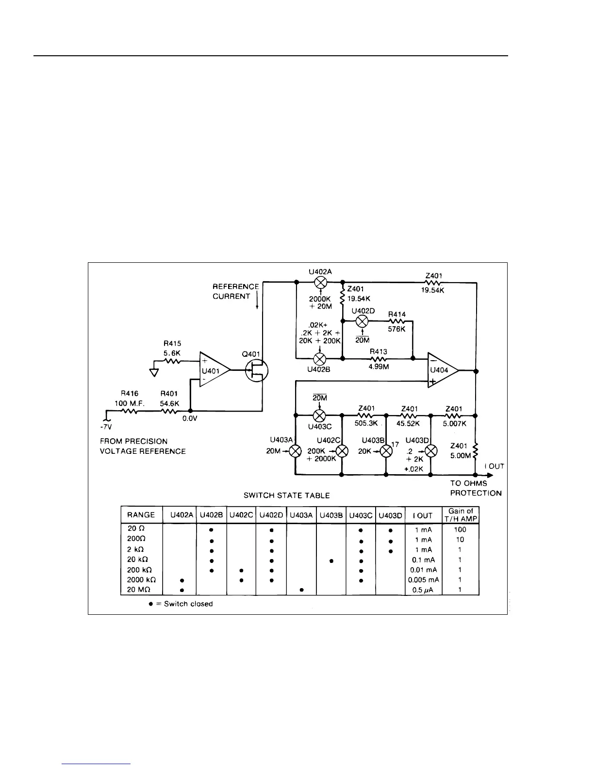
5-15. OHMS CURRENT SOURCE
The Ohms Current Source (Figure 5-7) provides a precise test current for the ohms
functions. The first stage (U401, R401, and Q401) produces a precise reference current,
using precision resistor R401 and a -7.0000V reference voltage from the Precision
Voltage Reference.
f5-07.wmf
Figure 5-7. Ohms Current Source