Maintenance
DISASSEMBLY PROCEDURE
6
6-25
f6-05.wmf
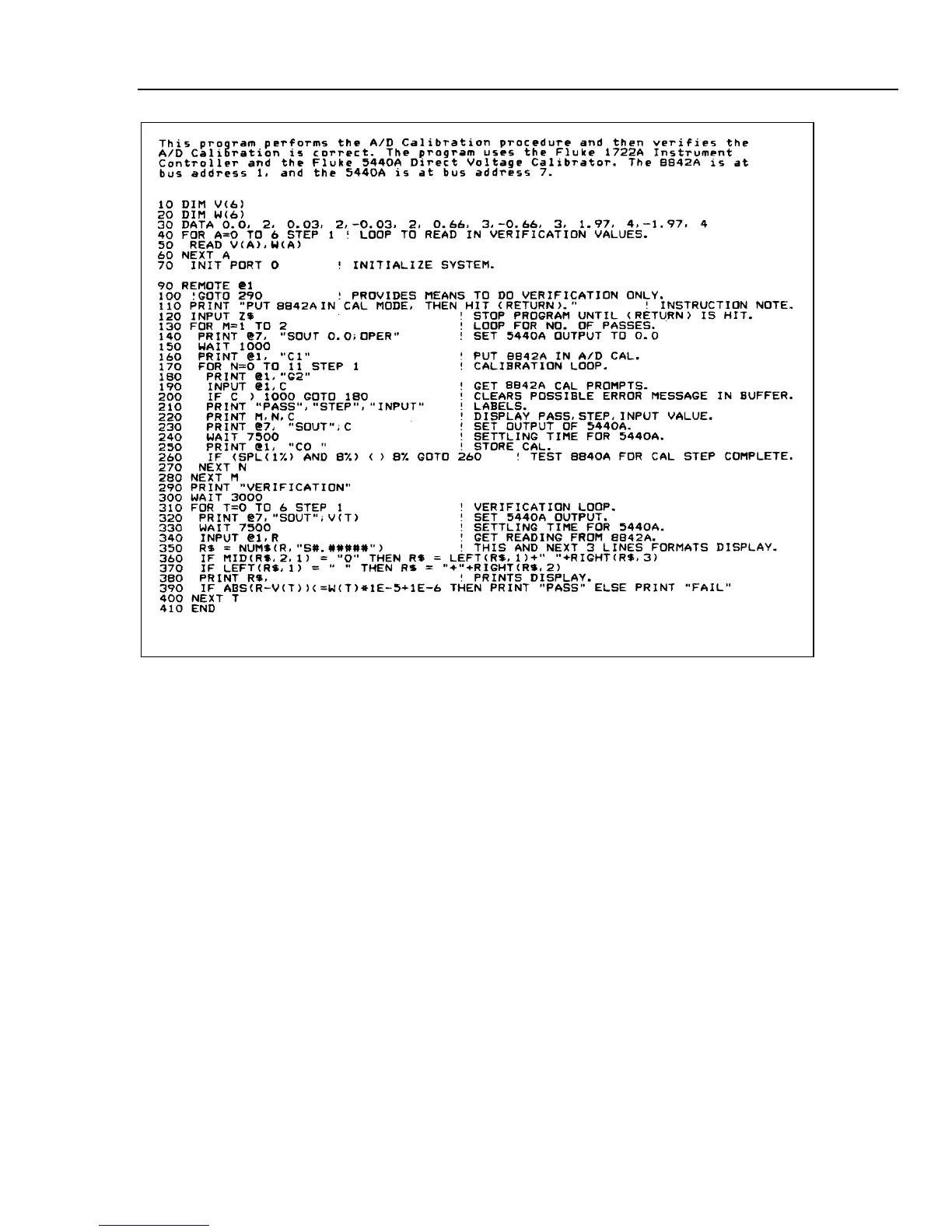
Figure 6-5. Example A/D Calibration Program
6-27. DISASSEMBLY PROCEDURE
WARNING
TO AVOID ELECTRIC SHOCK, REMOVE THE POWER CORD
AND TEST LEADS BEFORE DISASSEMBLING THE
INSTRUMENT. OPENING COVERS MAY EXPOSE LIVE PARTS.
CAUTION
To avoid contaminating the printed circuit assemblies (PCAs),
handle the PCAs by their edges. Do not handle the areas of the
PCAs that are not solder masked unless absolutely necessary.
These areas must be cleaned if contaminated.
The following paragraphs present a disassembly procedure for the 8842A. The procedure
should be performed in the order presented. Remove the case first, and then remove
Option -09, the True RMS AC PCA, Option -05, the IEEE-488 Interface PCA, the Main
PCA, and the front panel. For reference, see the final assembly drawing in Section 7.