EasyManuals Logo

Fluke 8842A User Manual

Fluke 8842A
269 pages
To Next Page IconTo Next Page
To Previous Page IconTo Previous Page
Page #199 background imageLoading...
Page #199 background image
8842A
Instruction Manual
6-62
f6-17.wmf
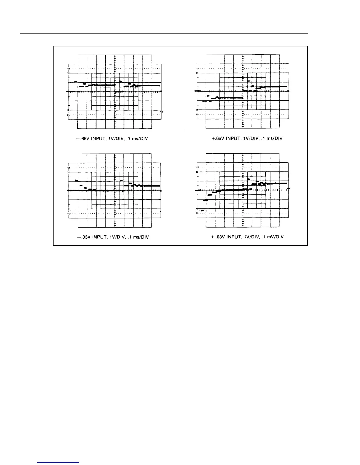
Figure 6-17. Waveforms at TP102 for Several Inputs on 2V DV Range
Since power supply problems can produce symptoms in many different sections of the
instrument, the first step in troubleshooting any problem should usually be a quick check
of the power supplies. For each power supply (TP801-TP806), check the level with a
voltmeter and check for ripple with an ac-coupled oscilloscope. The dc voltages should
be within the limits given in Table 6-23.
If a supply is too high, either its three-terminal regulator has failed or a fault elsewhere in
the instrument has shorted two supplies together. After repairing such a problem, make
certain that nothing else was damaged by the overvoltage.

Table of Contents

Questions and Answers:

Question and Answer IconNeed help?

Do you have a question about the Fluke 8842A and is the answer not in the manual?

Fluke 8842A Specifications

General IconGeneral
Maximum Voltage1000 V
Maximum Current2 A
Operating Temperature0°C to 50°C
Weight2.5 kg
DC Voltage Range100mV to 1000V
DC Current Range0 to 2 A
AC Current Range0 to 2 A
Frequency Range20 Hz to 20kHz
Basic Resistance Accuracy0.01%
Dimensions216mm x 88mm x 280mm
Resistance Range200 Ω to 20 MΩ

Related product manuals