CHARACTERISTICS
2-5
CHARACTERISTICS SPECIFICATIONS ADDITIONAL INFORMATION
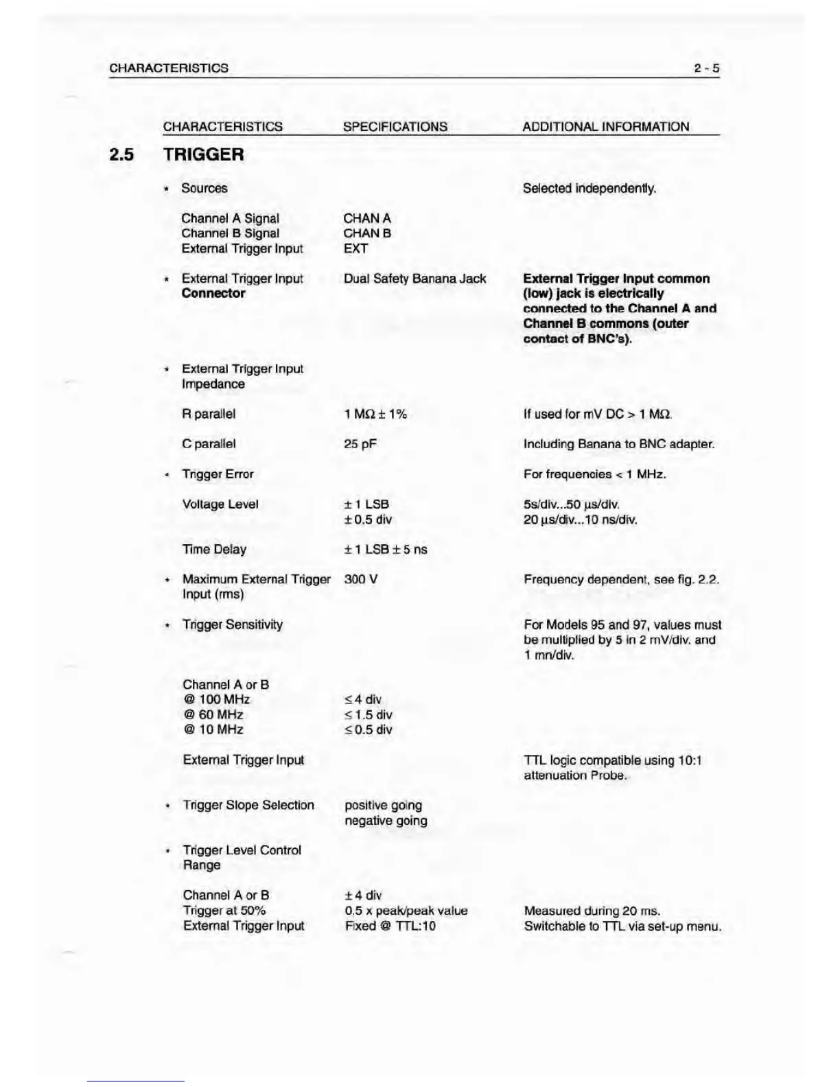
2.5 TRIGGER
•
Sources
Sheeted
Independently.
Channel
A
Signal
Channel B Signal
External Trigger Input
GHANA
CHAN B
EXT
*
External Trigger Input
Connector
Dual Salety Banana Jack External Trigger Input common
(low) jack is electrically
connected to the Channel A and
Channel B commons (outer
contact of BNC's).
'
External Tiigger Input
Impedance
R
parallel
1 MJ^±1% If used for mV DC
>
1 MQ.
C parallel
25
pF Including Banana to BNC adapter.
•
Trigger Error For frequencies < 1 MHz.
Voltage Level ±1 LSB
±0.5 div
5s;dlv...50MS/dlv.
20
|i8/div...10 ns/div.
Time Delay ±1 LSB
±5 ns
•
Maximum External Trigger
Input (rms)
300 V Frequency dependent, see fig. 2.2.
•
Trigger Sensitivity For
Models 95 and
97,
values must
be multiplied by 5 In 2 mV/dIv. and
1 mn/dfv.
Charrnel A or B
a 100 MHz
^ 60
MHz
@ 10 MHz
54 div
51.5 div
50.5 div
External Trigger input TTL logic compatible using
10;1
attenuation
Probe.
•
Trigger Slope Selection positive going
negative going
•
Trigger Level Control
Range
Channel
A or B
Trigger at 50%
External Trigger Input
±4 div
0.5 X peak/t^ak value
Fixed @ TTL:10
Measured during
20 ms.
Switchable
lo TTL via set-up menu.