CORRECTIVE MAINTENANCE 7-1
7
CORRECTIVE MAINTENANCE
7.1
DIAGNOSTIC TESTING
AND TROUBLESHOOTING
7.1.1 Introduction
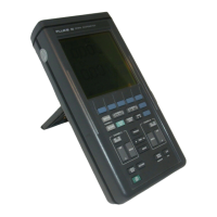
The ScopeMeter provides
semimodular design to aid in troubleshooting.
This section describes
procedures needed
to isolate a problem In a specific functional
area. Finally, troubleshooting hints for
each functional area are presented.
If the ScopeMeter fails, first
verify that you are operating the
ScopeMeter correctly by reviewing the
Operation Venficatlon
Procedure found in the Users Manual.
WARNING:
Opening the case may expose hazardous
voltages. Always disconnect the
instalment
from all voltage sources
and
remove
the batteries before opening the
case.
Remember that repairs or servicing should
be performed by qualified
personnel
only.
7.1 .2 Troubleshooting
techniques
If a fault appears, the following test sequence
can be used to help you to locate the defective
component:
•
Check
to verify that the control settings of the instrum^t
are correct. Consult the
operating
instructions
in the Users Manual.
•
Che<A the equipment
to which the ir^strument is connected
and check the interconnection cables.
•
Verify that the instrument
is properly calibrated. If It is not, refer
to Chapter 5: 'Calibration
Adjustment P^ocedure^
•
Locate the circuit{6)
in which you suspect the fault: the
symptom often suggests the faulty circuit.
If the power
supply is defective, the symptom may
appear to be caused by several circuts.
•
Check the drcult(s)
In which you suspect the fauH. Often it is
possible to find faults such as cold
or defective solder joints, intermittent
or open interconnection plugs and wires
or damaged
components.

 Loading...