3
•
18
CIRCUIT DESCRIPTIONS
3.4.4 EXTERNAL (BANANA) INPUT/OUTPUT circuitry
•
Introduction
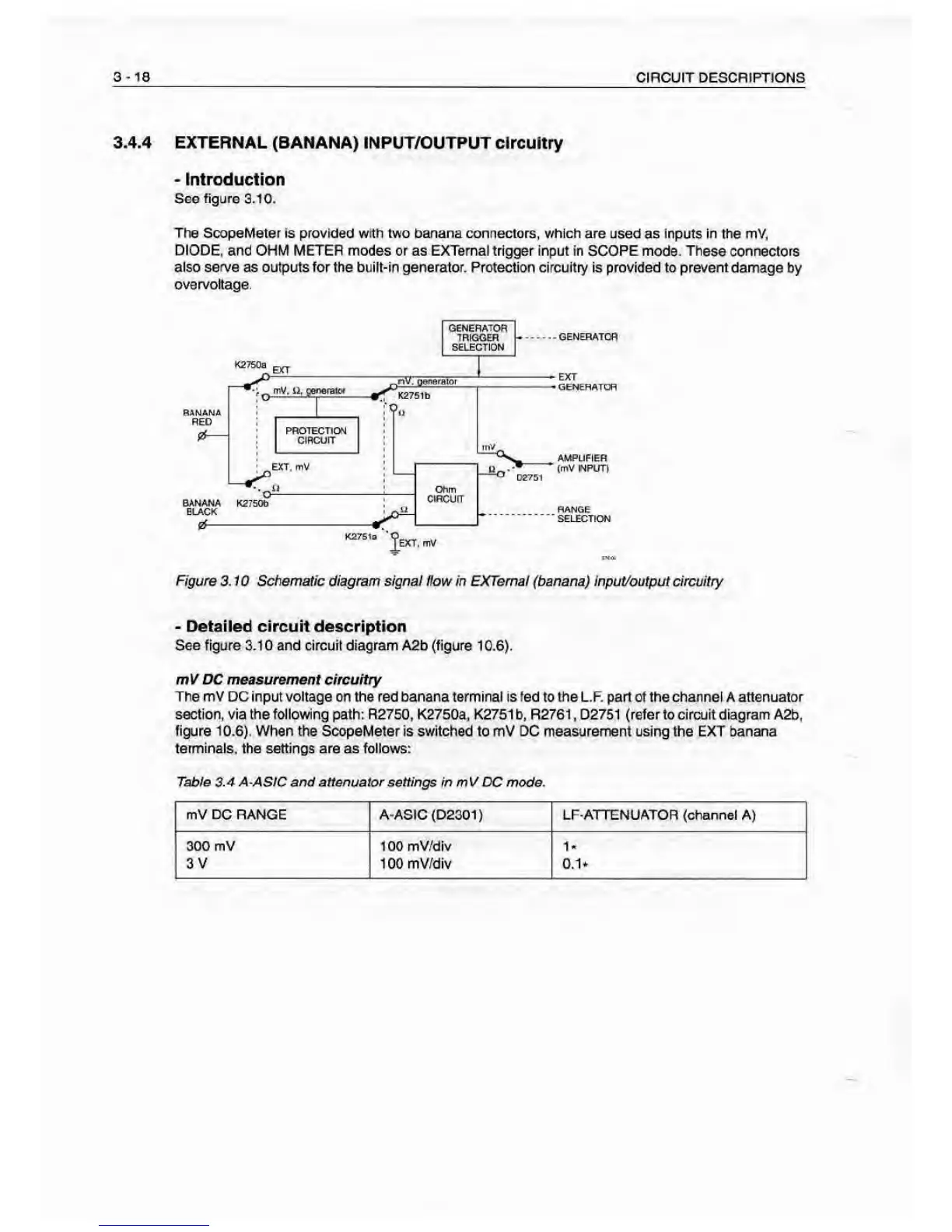
See figure 3.10.
The ScopeMeter Is provided with two Panana connectors, which are used
as
Inputs In
the mV,
DIODE, and OHM METER modes or as EXTerna I trigger inpirt in SCOPE mode. These connectors
also serve
as outputs for the built-in
generator.
Protection circuitry is provided to prevent damage
by
overvoltage.
t<27E1a
*0
Text, mv
Figure 3.10 Schematic diagram signal flow fn EXTemaf (banana) input/output circuitry
•
Detailed circuit deacription
See figure 3.1
0
and circuit diagram A2b (figure
10.6).
mV DC measurement circuitry
The
mV DC input
voltage
on the red banana terminal is
fed
to die L.F. pan of the channel A attenuator
section, via the followng path: R2750, K2750a, K2751 b, R2761
,
D2751 (refer to circurt diagram A2b,
figure 10.6). M/hen the ScopeMeter is switched to mV DC measurement using the EXT banana
terminals, the settings are
as
follows:
Table $.4 A-ASIC and attenuator settings in
mV
DC
mode.
mV
DC
RANGE A-ASIC (02301) LF-ATTENUATOR (channel A)
300
mV
I
100
mV/div
1-
3 V 100 mV/dIv O.V