CIRCUIT DESCRIPTIONS
3-19
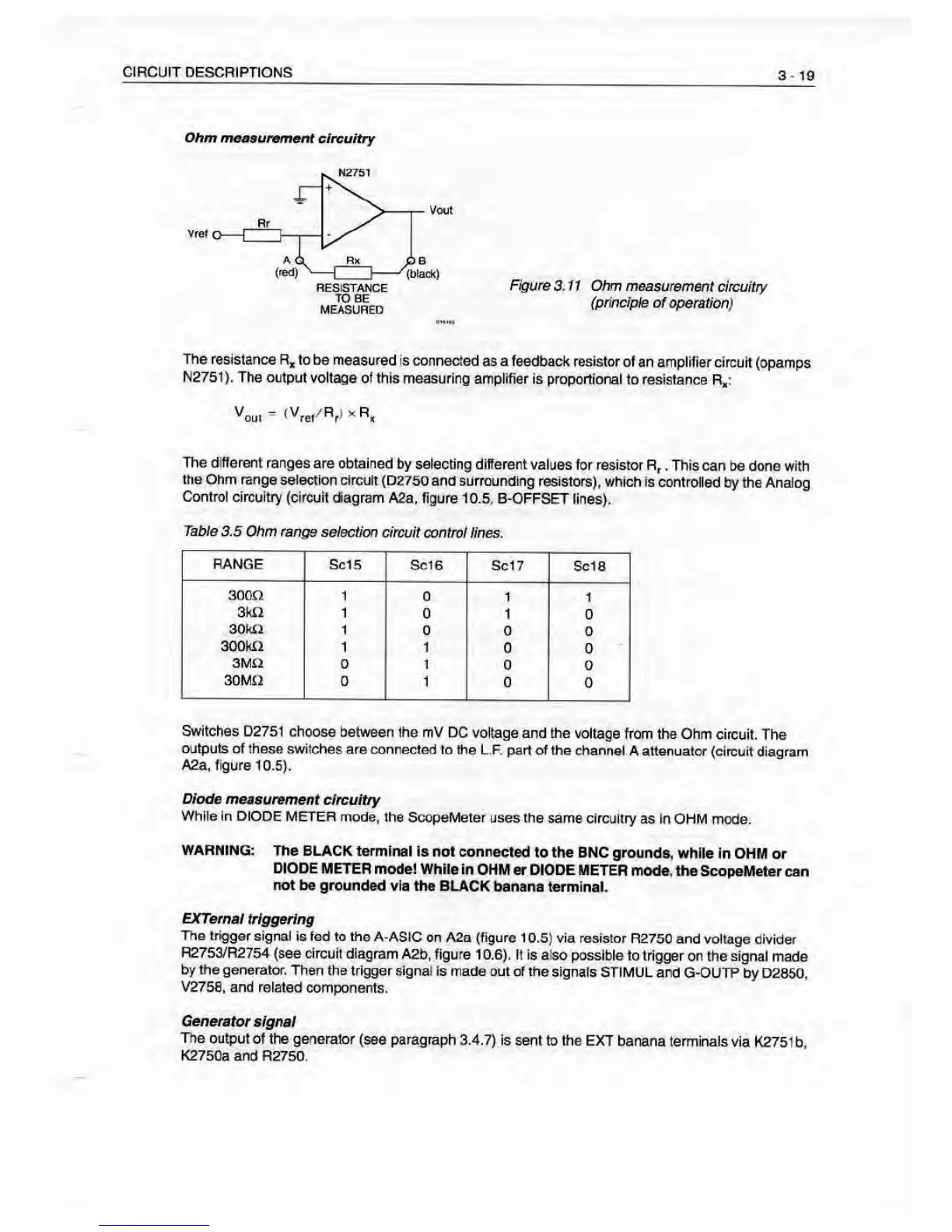
Ohm measurement
circuitry
n«i9»
Figure
3.11 Ohm measurement
circuitry
(principie of operation)
The resistance
R* to be measured
is connected
as a feedback resistor of
an amplrfier circuit
(opamps
N2761). The output
voltage of this measuring
amplifier Is proportional
to resistance R,:
VoLj.
=
<Vret''Rrt’'R«
The different ranges
are obtained
by selecting different values
for resistor R,
,
This
can be done with
ine Ohm range
selection circuit (D2750
and surroundmg resistors),
which Is controlled
by the Analog
Control circuitry (circuit
dagram A2a,
figure 10.5, B-OFFSET
lines).
Table 3.5
Ohm
range
selection
circuit control lines.
RANGE Sc15
Sc16 Set 7
Sole
300Q 1
0 1
1
3kii
1
1
0
30k£2
1
0 0
0
300W2
1 1
0
3MO
0 1
0
0
30MI2
0 1
0
Switches D2751 choose
between the mV DC
voltage and the voltage
from the Ohm circuit.
The
outputs
of these sv/itches are connected to the
L.F. part of the channel
A attenuator (circuit
diagram
A2a, figure
10.5).
Diode measurement
circuitry
While In DIODE
METER mode, the
ScopeMeter uses the
same circuitry as
In OHM mode.
WARNING:
The BLACK terminal
id not connected
to the BNC grounds,
while in OHM
or
DIODE METER
mode! While in
OHM er DIODE METER
mode, the ScopeMeter
can
not be grounded
via the BLACK
banana terminal.
EXTernai
trlggerirjg
The trigger
signal is fed to the
A-AStC on A2a (figure 1
0.6)
via resistor
R2750 and voltage divider
R2763/R2754
(see circuit diagram
A2b, figure 10.6). It Is also
possible to trigger
on the signal made
by frie generator.
Then the trigger signal
Is made out of the
Signals STIMUL and
G-OUTP by D2S60.
V2758, and related
components.
Generator
signal
The output
of the generator
(see paragraph
3.4,7) is sent to the EXT
banana terminals via
K2751 b.
K2750a and R2760.